 CEMarked CEMarked
Designed to suppress low-frequency DC bus ripple, prevent continuous current discontinuities, and safeguard variable frequency inverters against thermal overload and transient commutation notches.
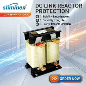
Pure electrolytic copper foil winding engineered for high-duty frequency drives, providing harmonic mitigation, ripple current smoothing, and superior thermal stability up to 1000V systems.
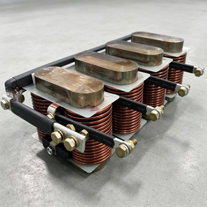
Built with amorphous alloy ribbon cores delivering high saturation flux density and up to 70% lower iron losses at intermediate frequencies, ideal for high-power DC traction and rectifiers.
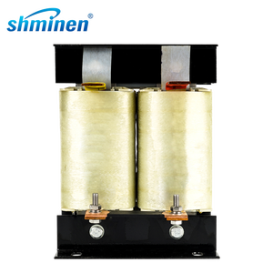
Optimized aerospace-grade aluminum winding configuration designed for standard 1.5 kW to 380 kW converter topologies, achieving balanced weight-to-impedance ratio and thermal endurance.
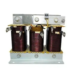
High-flexibility soft connection cabling system facilitating rapid enclosure integration, minimal busbar mechanical strain, and high vibration tolerance in heavy mobile machinery.
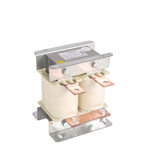
Specialized single-phase DC link inductors incorporating inter-turn insulation barriers, designed to eliminate capacitive switching spikes and radio frequency interference in compact automation setups.
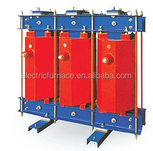
Ruggedized magnetic core architecture tailored for utility rectifiers, electrochemical plants, and heavy metallurgical variable speed drives requiring continuous operation under extreme harmonics.
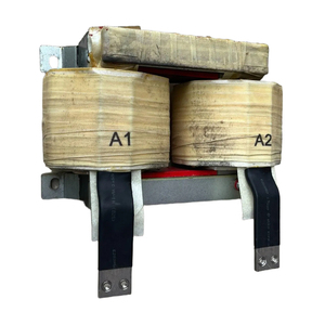
Calibrated precision inductor with tight ±10% inductance tolerances, calibrated specifically for direct replacement in PLC, CNC, and high-precision automation power supply stages.
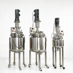
Complete heavy chemical and resin reaction vessel system featuring automated drive controls, explosion-proof electric stirring, and heat exchange jackets for insulation varnishing operations.
An authoritative technical breakdown for power electronics designers, electrical engineers, and global procurement teams specifying DC link magnetic components.
In three-phase full-bridge rectifier circuits, rectified direct current is naturally overlaid with alternating voltage harmonics at fundamental frequencies of $6f$ (300 Hz in 50 Hz systems, 360 Hz in 60 Hz grids). The DC smoothing reactor introduces frequency-dependent inductive reactance ($X_L = 2\pi f L$), creating an impedance divider across the DC bus. This dampens AC ripple amplitude, reduces total harmonic distortion (THD-i), and protects DC-link film or electrolytic capacitors from destructive ripple-current heat buildup.
At light electrical loads, rectifiers tend to transition into discontinuous conduction mode (DCM), causing peak output voltage to float upward to $\sqrt{2} \times V_{line}$, severely stressing insulated-gate bipolar transistors (IGBTs). Sizing the smoothing reactor inductance above the critical value ($L_c$) guarantees continuous conduction mode (CCM) across the entire operational range, stabilizing DC link voltage and preventing control-loop instability in modern drive topologies.
During sudden inverter bridge shoot-through, external DC bus short circuits, or rapid dynamic load steps, the DC link choke provides instantaneous reactive opposition to current ramp rates according to Faraday's law ($v = L \cdot di/dt$). This rate-of-rise damping buys essential microseconds for electronic threshold sensors and gate drive protection circuits to trip safely without catastrophic fuse rupture or explosive silicon failure.
Comparative evaluation of magnetic cores used across Chinese manufacturing facilities.
| Core Material Architecture | Saturation Flux ($B_{sat}$) | Relative Core Loss ($P_{fe}$) | Typical Freq. Band | Thermal Stability | Prime Industrial Application |
|---|---|---|---|---|---|
| Cold-Rolled Grain-Oriented (CRGO) | 1.9 – 2.03 Tesla | Moderate (1.0 – 1.4 W/kg) | 50 Hz – 400 Hz | Class F (155°C) / H (180°C) | Standard industrial VFDs, utility rectifiers, mining drives |
| Amorphous Metal Ribbon (Fe-Based) | 1.56 – 1.62 Tesla | Ultra-Low (0.2 – 0.35 W/kg) | 300 Hz – 20 kHz | Class H (180°C) | Renewable energy solar/wind inverters, high-efficiency UPS |
| Nanocrystalline Magnetic Alloy | 1.23 – 1.28 Tesla | Extremely Low (<0.18 W/kg) | 1 kHz – 100 kHz | Class H / Class C (200°C) | High-frequency active front ends, railway traction DC buses |
| Air-Core (Gapped Phenolic/Epoxy) | Linear (No Saturation) | Zero Magnetic Loss | DC to Ultra-High Freq | Class H / Exterior Grade | Pulsed power facilities, HVDC converter terminal filtering |
Backed by 25+ years of engineering experience, a sprawling 5,500 m² clean production plant, and an exhaustive computerized inspection protocol.
Our dedicated manufacturing base houses precision automated foil winding machinery, multi-vacuum pressure impregnation (VPI) autoclaves, and high-capacity drying ovens, providing complete batch-to-batch consistency and insulation integrity.
Every reactor undergoes automated open-circuit and short-circuit testing, high-accuracy digital LCR inductance validation, and milli-ohm winding resistance analysis to ensure tight ±5% or ±10% compliance before dispatch.
Equipped with Double Voltage Double Frequency (DVDF) induced overvoltage test rigs and automated Megger insulation resistance testers up to 5000V, ensuring breakdown-proof isolation under prolonged industrial overvoltages.
All reactor series are manufactured to strict IEC 60076-6 and EN 61558-2-20 international standards, bearing verifiable CE markings and export certifications demanded by European, American, and Asian EPC contractors.
Strategic technology shifts transforming industrial magnetics procurement through 2026–2030.
As Silicon Carbide (SiC) and Gallium Nitride (GaN) devices replace traditional silicon IGBTs, carrier switching frequencies are jumping from 2–4 kHz up to 20–50 kHz. This allows reactors to decrease physical volume by over 40% while placing premium value on ultra-thin lamination amorphous alloys and low-capacitance distributed winding geometries to mitigate skin-effect losses.
The global push for green hydrogen generation requires massive megawatt-scale DC rectifiers operating under extremely high continuous current (often exceeding 5,000A to 10,000A at low DC voltages). Procurement specifications are shifting heavily toward liquid-cooled and force-ventilated copper-foil smoothing reactors capable of suppressing current ripples below 2% to protect expensive electrolyzer membrane stacks.
International industrial EPCs now demand Finite Element Method Magnetics (FEMM) and 3D CFD thermal simulation reports prior to contract signing. Factory sourcing contracts require comprehensive temperature-rise verification using calibrated infrared thermography and integrated PT100/PT1000 sensors embedded directly within the reactor core air gaps.
Follow this structured five-step calculation and verification methodology when requesting custom quotes.
Identify the converter topology (e.g., 6-pulse, 12-pulse, or active rectifier). Determine the fundamental ripple frequency ($f_r = p \cdot f_{grid}$) and measure the peak-to-peak ripple voltage ($\Delta V_{dc}$) present across the uncontrolled rectifier bridge.
Determine allowable ripple current percentage ($\%I_{ripple}$), typically between 2% and 10% of rated DC load current ($I_{dc}$). Use the core inductance equation:
$$L = \frac{V_{ripple}}{2\pi \cdot f_{ripple} \cdot \Delta I_{pp}}$$
Ensure the reactor core maintains at least 90% of nominal inductance at 120% full rated DC current, and does not hard-saturate under 150% peak transient conditions. Specify thermal insulation classes (Class F 155°C or Class H 180°C) with minimum IP00 to IP54 enclosure ratings.
Direct answers to clarify specifications, quality standards, and logistical considerations.
An AC line reactor is installed at the inverter or converter input (three-phase AC side) to reduce supply grid harmonics, dampen line spikes, and buffer notches. A DC smoothing reactor (or DC link choke) is connected on the positive or negative rail of the internal DC bus. It specifically filters out the rectified DC ripple current, smooths the continuous conduction current, and protects the DC bus capacitors from over-temperature failure.
Copper core reactors deliver superior electrical conductivity, smaller footprint (up to 30% more compact), and lower thermal expansion, making them ideal for space-constrained VFD cabinets and high vibration settings. Aluminum core reactors offer a substantial cost advantage and lighter weight, performing equally well provided the conductor cross-section and thermal cooling channels are properly sized by factory designers.
Because DC smoothing reactors carry continuous unidirectional direct current, un-gapped magnetic cores would quickly push into magnetic saturation ($B_{sat}$), collapsing inductance to near zero. By inserting precision non-magnetic air gaps (phenolic resin, Nomex, or ceramic spacers) evenly across the core limbs, the magnetic reluctance is increased, flattening the B-H curve and enabling linear inductance up to high operating currents.
Every certified batch from our factory is supplied with a comprehensive quality dossier containing: (1) Cold Winding Resistance Test (Milli-ohm meter), (2) Inductance vs. Rated Current Curve (LCR bridge), (3) Insulation Resistance (Megger 1kV–5kV), (4) Double Voltage Double Frequency (DVDF) induced overvoltage test, and (5) Temperature Rise verification data according to IEC 60076 standards.
To receive an exact design drawing and price proposal, provide: Rated DC operating voltage ($V_{dc}$), rated continuous DC current ($I_{dc}$), peak ripple frequency (Hz), required inductance rating ($mH$ or $\mu H$), permissible ripple current ($\Delta I$), ambient temperature, preferred cooling method (AN/AF/WF), and target terminal termination style.
DC link reactors are subject to alternating electromagnetic forces that cause mechanical vibration and acoustic humming. We eliminate noise pollution below 65 dB through grain-oriented steel step-lap stacking, multi-point non-magnetic clamping studs, distributed multi-gap core geometries, and complete vacuum pressure impregnation (VPI) with high-damping solventless epoxy resin.
Whether you require standard 3A–3000A DC link chokes, specialized amorphous reactors for high-frequency converters, or customized heavy-power magnetics for industrial drives, our factory engineering team is ready to review your schematics and deliver customized CAD drawings within 24 hours.
Get a Quote