
Rugged 3-Phase Reactors for VFD Harmonic Suppression & Motor Protection
Prima RL Series Line and Load Reactors represent an engineered, cost-effective solution for eliminating damaging power line disturbances, voltage spikes, and harmonic distortion across variable frequency drives (VFDs) and sensitive industrial automation equipment.
Built with premium-grade electrical silicon steel laminations, high thermal-class copper or aluminum windings, and robust insulation barriers, our reactors operate continuously under harsh industrial electrical environments. Whether mounted at the drive input (line side) or output (load side), they optimize true power factor, eliminate nuisance trip interruptions, and safeguard critical downstream motors against premature insulation breakdown.
- Full Current Range: 1A to 2500A @ 40°C ambient continuous
- Targeted Impedance: Standard 0.5% to 7% (3% & 5% available)
- IEEE 519 Compliant: Significant low-order THDi harmonic reduction
- Overload Capacity: 200% rated current withstand for 30s
- Low Watt Loss: Precision gap geometry reduces thermal dissipation
- Global Export Ready: CE marked with 3000VAC hi-pot proof testing
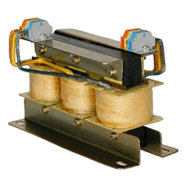
Line Reactors vs. Load Reactors: Technical Functions
Understanding where and why reactors are installed in an adjustable speed drive architecture is critical to maximizing drive train longevity.
Line Reactor (Input Side)
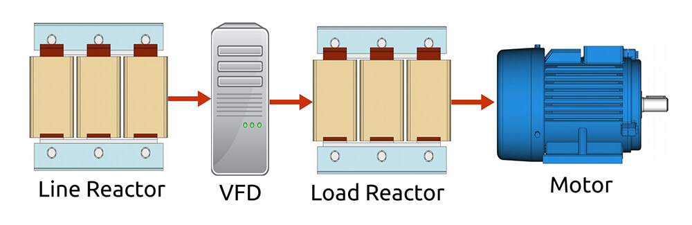
Installed directly between the incoming AC line power and the input terminals of the VFD rectifier to protect the drive against grid phenomena and lower utility-side disturbance.
- Attenuates Harmonic Distortion: Filters 5th, 7th, 11th, and 13th current harmonics to assist compliance with IEEE 519 standards.
- Surge & Transient Suppression: Absorbs voltage spikes and utility capacitor switching surges that cause overvoltage DC-bus tripping.
- Limits Inrush Current: Restricts steep peak currents during drive energization, extending the operating life of input bridge rectifiers and DC-link capacitors.
- Mitigates Commutation Notching: Smoothes notches created by SCR switching across shared industrial distribution busses.
- Improves Power Factor: Raises the true operational power factor of non-linear drive loads.
Load Reactor (Output Side)
Positioned between the PWM inverter output terminals of the VFD and the motor leads to dampen high-frequency pulse reflections and severe dv/dt stress.
- Mitigates dv/dt Stress: Slows down ultra-fast voltage rise times (dv/dt), shielding motor turn-to-turn winding insulation from puncture.
- Dampens Peak Reflections: Prevents reflected wave voltage doubling on motor cable runs exceeding 30 to 100 meters.
- Reduces Motor Operating Temperature: Lowers high-frequency eddy current losses inside the motor laminations, decreasing thermal stress.
- Acoustic Noise Reduction: Dampens high-frequency motor whining and mechanical resonance within stator slots.
- Short-Circuit Buffer: Provides valuable microsecond delay margins during accidental load shorts before drive trip thresholds fire.
Below illustrates standard electrical integration: the Input Line Reactor shields the drive's rectifier stage from incoming mains distortion, while the Output Load Reactor protects motor windings from high-frequency inverter switching spikes.
Harmonic Attenuation vs. Reactor Impedance
Line reactor impedance directly determines harmonic current mitigation efficiency. Higher impedance reduces harmonic spectrum amplitude at the trade-off of nominal voltage drop across the reactor coils.
| Harmonic Order (I) | 0.50% | 1.0% | 2.0% | 3.0% | 4.0% | 5.0% | 6.0% | 7.0% | 8.0% | 9.0% | 10.0% |
|---|---|---|---|---|---|---|---|---|---|---|---|
| 5th Harmonic (%) | 80.0 | 60.0 | 46.0 | 40.0 | 34.0 | 32.0 | 30.0 | 28.0 | 26.0 | 24.0 | 23.0 |
| 7th Harmonic (%) | 60.0 | 37.0 | 22.0 | 16.0 | 13.0 | 12.0 | 11.0 | 10.0 | 9.0 | 8.3 | 7.5 |
| 11th Harmonic (%) | 18.0 | 12.0 | 9.0 | 7.3 | 6.3 | 5.8 | 5.2 | 5.0 | 4.3 | 4.2 | 4.0 |
| 13th Harmonic (%) | 10.0 | 7.5 | 5.8 | 4.9 | 4.2 | 3.9 | 3.6 | 3.3 | 3.15 | 3.0 | 2.8 |
| 17th Harmonic (%) | 7.3 | 5.2 | 3.6 | 3.0 | 2.4 | 2.2 | 2.1 | 0.9 | 0.7 | 0.5 | 0.4 |
| 19th Harmonic (%) | 6.0 | 4.2 | 2.8 | 2.2 | 2.0 | 0.8 | 0.7 | 0.4 | 0.3 | 0.25 | 0.2 |
| % THD (Total Harmonic Distortion) | 102.5% | 72.2% | 52.3% | 44.13% | 37.31% | 34.96% | 32.65% | 30.35% | 28.04% | 25.92% | 24.68% |
*Note: Data calculated at nominal rated full load on standard six-pulse rectifier bridge topologies. 3% and 5% impedance reactors represent optimal balance between THDi suppression and operational bus voltage stability.
Selection Guide: Three-Phase Line Reactors
Standard design ratings for 415V / 50Hz applications. Custom inductance values, 690V ratings, and higher kW configurations are engineered upon project request.
| Motor Power (HP) | Rating (kW) | Inductance (mH) | Rated Current (A) | L (mm) | B (mm) | H (mm) | Mounting X (mm) | Mounting Y (mm) | Slot (mm) | Weight (kg) | Frame |
|---|---|---|---|---|---|---|---|---|---|---|---|
| 1.0 HP | 0.75 kW | 6.10 mH | 2.4 A | 150 | 100 | 100 | 122 | 45 | 8 x 20 | 1.0 | Type A |
| 2.0 HP | 1.5 kW | 3.10 mH | 4.0 A | 125 | 90 | 100 | 76 | 50 | 8 x 20 | 1.1 | Type A |
| 3.0 HP | 2.2 kW | 2.24 mH | 6.3 A | 125 | 90 | 100 | 76 | 60 | 8 x 20 | 1.6 | Type A |
| 4.0 HP | 3.0 kW | 1.55 mH | 9.1 A | 110 | 90 | 100 | 75 | 60 | 8 x 20 | 1.6 | Type A |
| 5.0 HP | 4.0 kW | 1.26 mH | 11.2 A | 160 | 125 | 130 | 130 | 50 | 8 x 20 | 2.4 | Type A |
| 7.5 HP | 5.5 kW | 0.881 mH | 16.0 A | 160 | 120 | 130 | 130 | 50 | 8 x 20 | 2.7 | Type A |
| 10.0 HP | 7.5 kW | 0.783 mH | 18.0 A | 160 | 140 | 65 | 130 | 60 | 8 x 20 | 3.3 | Type B |
| 15.0 HP | 11.0 kW | 0.503 mH | 28.0 A | 160 | 150 | 65 | 130 | 65 | 8 x 20 | 3.9 | Type B |
| 20.0 HP | 15.0 kW | 0.397 mH | 35.5 A | 230 | 160 | 180 | 195 | 72 | 8 x 20 | 5.0 | Type B |
| 25.0 HP | 18.5 kW | 0.352 mH | 40.0 A | 190 | 175 | 200 | 160 | 70 | 8 x 20 | 8.0 | Type B |
| 30.0 HP | 22.0 kW | 0.282 mH | 50.0 A | 190 | 170 | 200 | 160 | 70 | 8 x 20 | 6.5 | Type B |
| 40.0 HP | 30.0 kW | 0.224 mH | 63.0 A | 195 | 190 | 200 | 160 | 80 | 8 x 20 | 8.7 | Type B |
| 50.0 HP | 37.0 kW | 0.176 mH | 80.0 A | 315 | 170 | 215 | 225 | 135 | 13 x 28 | 12.1 | Type C |
| 60.0 HP | 45.0 kW | 0.141 mH | 100.0 A | 225 | 160 | 210 | 190 | 75 | 13 x 28 | 15.8 | Type C |
| 75.0 HP | 55.0 kW | 0.113 mH | 125.0 A | 230 | 160 | 215 | 190 | 80 | 8 x 20 | 15.8 | Type C |
| 100.0 HP | 75.0 kW | 0.0881 mH | 160.0 A | 225 | 155 | 210 | 190 | 95 | 8 x 20 | 20.3 | Type C |
| 120.0 HP | 90.0 kW | 0.0704 mH | 200.0 A | 240 | 170 | 210 | 190 | 95 | 8 x 20 | 21.5 | Type C |
| 150.0 HP | 110.0 kW | 0.0629 mH | 224.0 A | 225 | 175 | 210 | 190 | 100 | 8 x 20 | 24.8 | Type C |
| 175.0 HP | 132.0 kW | 0.0503 mH | 280.0 A | 300 | 210 | 275 | 200 | 100 | 13 x 28 | 31.8 | Type D |
| 215.0 HP | 160.0 kW | 0.0440 mH | 315.0 A | 300 | 175 | 270 | 200 | 90 | 13 x 28 | 32.4 | Type D |
| 270.0 HP | 200.0 kW | 0.0352 mH | 400.0 A | 300 | 180 | 270 | 200 | 130 | 13 x 28 | 43.1 | Type D |
Selection Guide: Three-Phase Load Reactors
Engineered for inverter output duty to dampen dv/dt surges on motor terminals. Dimensions provided in open frame construction.
| Motor Power (HP) | Rating (kW) | Inductance (mH) | Rated Current (A) | L (mm) | B (mm) | H (mm) | Mounting X (mm) | Mounting Y (mm) | Slot (mm) | Weight (kg) | Frame |
|---|---|---|---|---|---|---|---|---|---|---|---|
| 1.0 HP | 0.75 kW | 5.050 mH | 2.0 A | 125 | 85 | 95 | 75 | 55 | 8 x 20 | 1.0 | Type A |
| 1.5 HP | 1.1 kW | 5.200 mH | 4.0 A | 125 | 85 | 95 | 75 | 55 | 8 x 20 | 1.1 | Type A |
| 3.0 HP | 2.2 kW | 3.400 mH | 6.1 A | 150 | 90 | 120 | 103 | 55 | 8 x 20 | 2.2 | Type A |
| 4.0 HP | 3.0 kW | 1.243 mH | 10.2 A | 125 | 100 | 95 | 78 | 68 | 8 x 20 | 1.6 | Type A |
| 5.0 HP | 4.0 kW | 1.243 mH | 10.2 A | 125 | 100 | 95 | 78 | 68 | 8 x 20 | 1.6 | Type A |
| 7.5 HP | 5.5 kW | 0.483 mH | 17.5 A | 150 | 85 | 160 | 100 | 50 | 8 x 20 | 1.8 | Type A |
| 10.0 HP | 7.5 kW | 0.483 mH | 17.5 A | 150 | 85 | 160 | 100 | 50 | 8 x 20 | 1.8 | Type A |
| 15.0 HP | 11.0 kW | 0.332 mH | 25.5 A | 140 | 90 | 155 | 100 | 55 | 8 x 20 | 2.4 | Type B |
| 20.0 HP | 15.0 kW | 0.249 mH | 34.0 A | 230 | 145 | 175 | 195 | 73 | 8 x 20 | 3.5 | Type B |
| 25.0 HP | 18.5 kW | 0.180 mH | 47.0 A | 230 | 160 | 180 | 195 | 75 | 8 x 20 | 3.8 | Type B |
| 30.0 HP | 22.0 kW | 0.180 mH | 47.0 A | 230 | 160 | 180 | 195 | 75 | 8 x 20 | 3.8 | Type B |
| 40.0 HP | 30.0 kW | 0.059 mH | 72.0 A | 190 | 140 | 145 | 160 | 63 | 8 x 20 | 4.5 | Type B |
| 50.0 HP | 37.0 kW | 0.059 mH | 72.0 A | 190 | 140 | 145 | 160 | 63 | 8 x 20 | 4.5 | Type B |
| 60.0 HP | 45.0 kW | 0.046 mH | 92.0 A | 195 | 160 | 145 | 160 | 64 | 8 x 20 | 4.8 | Type C |
| 75.0 HP | 55.0 kW | 0.029 mH | 146.0 A | 185 | 140 | 140 | 160 | 70 | 8 x 20 | 7.7 | Type C |
| 100.0 HP | 75.0 kW | 0.029 mH | 146.0 A | 185 | 140 | 140 | 160 | 70 | 8 x 20 | 7.7 | Type C |
| 120.0 HP | 90.0 kW | 0.023 mH | 186.0 A | 195 | 140 | 150 | 160 | 82 | 8 x 20 | 9.5 | Type C |
| 150.0 HP | 110.0 kW | 0.016 mH | 260.0 A | 230 | 145 | 215 | 190 | 70 | 8 x 20 | 14.9 | Type D |
| 175.0 HP | 132.0 kW | 0.016 mH | 260.0 A | 230 | 145 | 215 | 190 | 70 | 8 x 20 | 15.4 | Type D |
| 215.0 HP | 160.0 kW | 0.013 mH | 315.0 A | 225 | 155 | 215 | 190 | 85 | 8 x 20 | 18.3 | Type D |
| 270.0 HP | 200.0 kW | 0.011 mH | 370.0 A | 220 | 150 | 215 | 190 | 75 | 8 x 20 | 19.3 | Type D |
*Engineering notice: Capacities above 200kW up to 2500A are fully customized based on client duty-cycle specifications. Physical dimensions are subject to final submittal approval.
Key Application Sectors
Trusted across demanding industrial drive panels, MCC lineups, and renewable power converters worldwide.
Frequently Asked Technical Questions
What is the primary difference between a line reactor and a load reactor?
A line reactor is wired directly between the incoming mains AC supply and the VFD input bridge. It blunts incoming mains surges, prevents nuisance DC bus overvoltage tripping, reduces low-order THDi harmonics, and improves system power factor. A load reactor is positioned between the VFD inverter output and the electric motor terminals. Its primary role is to dampen steep dv/dt voltage spikes, reduce peak motor terminal voltages caused by reflected wave phenomena, quiet motor audible whining, and prevent premature insulation breakdown over long motor cables.
When should I choose 3% impedance versus 5% impedance reactors?
A 3% impedance reactor is recommended for standard industrial electrical installations to absorb moderate power grid spikes and decrease current harmonics by approximately 30% to 35%. A 5% impedance reactor should be specified when stricter compliance with IEEE 519 harmonic standards is required, when the drive is connected to a soft or stiff high-capacity power bus with high short-circuit capability, or on the load side when motor cable runs exceed 30 meters (100 feet).
How do line reactors assist with IEEE 519 compliance?
Non-linear six-pulse VFD rectifiers create pronounced 5th, 7th, 11th, and 13th current harmonics that propagate back into the utility power feed. Adding a properly sized 3% or 5% line reactor introduces inductive impedance that rounds off the discontinuous rectangular current draw into a smoother sinusoidal waveform, cutting total current harmonic distortion (THDi) down from >80% to between 30% and 40%.
What quality and dielectric routine tests are performed on each reactor?
Prior to export packaging, 100% of our reactors undergo rigorous in-house computerized testing: 3000 VAC phase-to-earth and phase-to-phase dielectric withstand tests for 3 seconds, digital LCR inductance testing under frequency, micro-ohm winding resistance balancing, and temperature-rise verification under full rated current.
Direct Technical Consultation for Global Engineering Teams
Need customized impedance values, high-voltage 690V line reactors, or bespoke sheet-steel enclosed chokes? Our application engineers provide rapid sizing assistance, thermal analysis, and commercial quotations within 24 hours.
Contact Us