What Is an Industrial Control Transformer, and How Do You Size and Source It for Demanding Automation Systems?
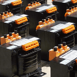
In modern electrical systems and industrial automation cabinets, an industrial Control Transformer (frequently referred to by electrical engineers as an Industrial Control Power Transformer or CPT) serves as the primary safeguard for sensitive electronics, pilot lights, PLCs, solenoid valves, and motor starters. Unlike general-purpose distribution transformers designed strictly for steady-state continuous thermal loads, a control transformer is distinctively engineered to withstand instantaneous, highly inductive inrush current demands without dropping the secondary voltage below critical operating thresholds.
When contactor coils, relays, or electromagnetic brakes pull in, their initial inrush current can reach 8 to 12 times their continuous sealed VA rating at extremely low power factors (frequently between 0.2 and 0.4 lagging). If the control transformer exhibits excessive internal leakage reactance or poor voltage regulation, the resulting voltage drop causes switchgear to chatter, contact welding, micro-processor resets in programmable logic controllers, and unpredictable safety lockouts. Sourcing the right control transformer requires evaluating secondary regulation curves, thermal endurance classes, short-circuit withstand capabilities, and galvanic safety separation.

Recommended Control Transformer Architectures & Configurations
Tailored configurations engineered for machine builders, switchgear integrators, and worldwide industrial power grids.
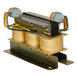
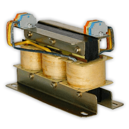
Multi-Tap Universal Control Transformers (50VA to 5000VA)
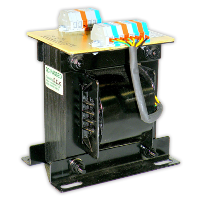
Built for machine tool exporters serving varied global power networks. Features tapped primary windings accommodating 208V, 240V, 380V, 415V, and 480V down to standard 110V, 120V, or 24V secondary control circuits.
- Core Lamination: High-grade cold-rolled non-grain-oriented (CRNGO) or CRGO electrical steel slitted in-house
- Transient Shielding: Integrated copper electrostatic Faraday shield to shunt high-frequency common-mode noise to ground
- Regulation: Exceptional output stability sustaining 95% nominal secondary voltage during peak contactor pull-in
- Compliance: Full conformance to IEC 61558-2-2 and UL 506 / UL 508A control circuit requirements
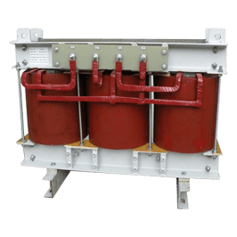
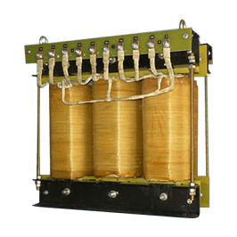
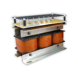
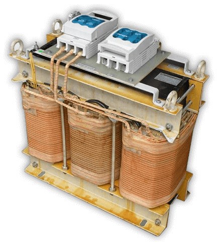
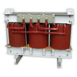
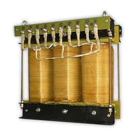
Heavy-Duty Three-Phase Control Transformers (1kVA to 50kVA)
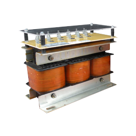
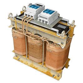
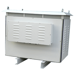
Engineered for complex centralized motor control centers (MCC), large-scale automation skids, and metallurgical plant switchgear requiring clean auxiliary three-phase and split single-phase supply lines.
- Coil Topology: Precision layer wound with electrolytic copper or high-conductivity electrical-grade aluminum
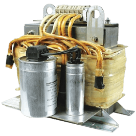
- Varnish Impregnation: Vacuum Pressure Impregnation (VPI) cycle with Class F (155°C) or Class H (180°C) thermosetting polyester resins
- Mechanical Integrity: Reinforced core clamping frames dampening electromagnetic acoustic hum and mechanical vibration
- Protection Readiness: Finger-safe IP20 touch-proof terminal blocks with integral fuse-block mounting capabilities
Technical Sizing Methodology: The Engineering Formula for Control Transformers
Electrical engineers must prevent premature tripping and contactor bounce by properly calculating both continuous thermal loading and instantaneous inductive inrush. Follow this two-step calculation standard:
Step 2: Total Peak Inrush VA = √ [ (Σ VA_sealed_continuous + Σ Inrush_VA_closing × cos θ)² + (Σ Inrush_VA_closing × sin θ)² ]
Where cos θ represents the low power factor (typically 0.3) of the coil during the mechanical pull-in phase. The selected control transformer must maintain secondary voltage at ≥ 90% of nominal rating on the manufacturer's regulation curve under this peak calculated VA vector. Prima Transformers designs its magnetic cores with low saturation flux density to deliver the required surge magnetics without inductive clipping.
Future Procurement Trends in Industrial Magnetics
How global automation mandates and supply chain evolution are reshaping control transformer procurement.

Global Decarbonization & Eco-Design Directives
Procurement directors in Europe and the Americas are actively enforcing stringent no-load core loss thresholds. The transition toward high-permeability, laser-treated grain-oriented silicon steels minimizes continuous standby excitation losses in 24/7 automated robotic cells and warehouse fulfillment centers.

IoT & Onboard Thermal Telemetry Integration
Future control transformers are no longer isolated passive iron-core units. OEM buyers increasingly specify built-in PT100/PT1000 RTD temperature sensors or NTC thermistors embedded directly in the secondary coil layers. These tie into PLC diagnostic modules for predictive condition monitoring and proactive thermal shutdown.

Nearshore & India Strategic Sourcing Diversification
To hedge against regional supply chain disruptions and volatile raw material freight costs, Fortune 500 automation manufacturers are diversifying magnetic component supply lines toward Indian manufacturing leaders who offer CE conformity, audited computerized testing, and vertically integrated coil winding infrastructure.
Control Transformer Technology: Key Development Trends
Next-generation engineering innovations that separate premium industrial magnetics from standard commercial wound components.
Advanced High-Dielectric Insulation Systems
The proliferation of variable speed drive systems within the same cabinet enclosure introduces repetitive high-frequency voltage spikes (dv/dt), reflected waves, and electromagnetic interference into control lines. State-of-the-art control transformers employ reinforced Nomex, mica barriers, and double-layer polyimide-coated Class H magnet wire. This advanced insulation configuration withstands inter-turn partial discharge breakdown and protects automation logic from catastrophic flashovers.
Compact Structural Footprints with Optimized Cooling
Real estate inside electrical control enclosures commands a premium price. Engineering advances in finite element magnetic modeling (FEMM) allow manufacturers to optimize the copper-to-iron mass ratio, reducing total unit weight and footprint by up to 22% while accelerating natural convective heat dissipation. Enhanced air-flow ducting within bobbin designs ensures that transformers maintain thermal equilibrium even in elevated 50°C ambient operating environments.