
Santej, Ahmedabad, Gujarat, India CE-Marked Transformers for Export
Serving OEMs & Projects Worldwide
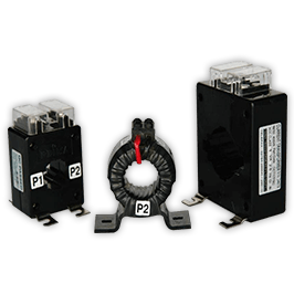
Industrial current transformer engineering plant background Precision current transformer for switchgear metering and relay protection
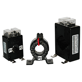
Precision instrument transformer manufacturing facility Molded window type current transformer ready for global export
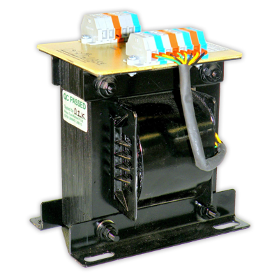
High power industrial testing infrastructure banner Industrial control and instrumentation magnetics
0+Years Magnetics Experience
0+Global OEMs Supplied
0 m²Testing & Production Plant
0.2SPrecision Accuracy Class
100%Computerized CT Routine Tested
Strategic Engineering Whitepaper

Current Transformer Sizing, Technology Trends & Procurement Intelligence for Global OEMs

25+

Years of parent-backed panel-builder DNA delivering CE-marked instrument transformers across 45+ international markets.

In modern electrical systems, the Current Transformer (CT) is the critical bridge between lethal medium/low-voltage primary power and sensitive microelectronic monitoring. Whether deploying numerical feeder protection, revenue billing metering, or real-time SCADA energy management, specification discrepancies can trigger catastrophic nuisance tripping, thermal runaway, or unmetered energy loss.

This technical guide synthesizes key engineering insights to resolve the most common questions raised by electrical consultants, EPC contractors, and global switchgear switchboard builders during instrument transformer procurement. Discover core magnetic trade-offs, knee-point voltage sizing, future-proof digital grid transitions, and how to configure optimal current transformers for harsh environmental conditions.

  • Class 0.2S / 0.5 metering vs 5P10 / 5P20 protection cores
  • Burden impedance matching & secondary saturation prevention
  • IEC 61869-2 & IEEE C57.13 compliance benchmarks
  • In-house computerized testing in our 5,500 m² Santej facility
Get Catalog View CT Specifications
Quality Assured Prima Transformers production plant in Santej Ahmedabad
Engineered Product Portfolio

High-Performance Current Transformers for Critical Applications

Engineered with silicon steel and high-permeability nickel-iron nanocrystalline cores to ensure precise linear saturation limits and superior dynamic thermal withstand.

Cast Resin & Epoxy Molded Current Transformers

Designed for indoor medium-voltage switchgear cubicles, outdoor distribution circuits, and dusty heavy-industry sites. Vacuum-impregnated or cast in hydrophobic cycloaliphatic epoxy resin, these units resist moisture ingress, thermal cycling cracking, and chemical corrosives.

  • Insulation Levels: 0.72kV, 3.6kV, 7.2kV, 12kV up to 36kV dry-type encapsulation
  • Core Configurations: Combined multi-core units (Core 1: 0.2S Metering; Core 2: 5P20 Protection)
  • Mechanical Integrity: High short-circuit electrodynamic strength withstanding 2.5 times Ith dynamic peak currents
  • Thermal Limits: Class B, F, or H insulation systems rated for continuous 120% ambient overload (Icth)

Precision Low Voltage Window & Busbar Ring CTs

Engineered for low-voltage Motor Control Centers (MCC), Power Control Centers (PCC), and high-amperage sub-distribution panels. Designed to slide cleanly over copper or aluminum busbars with vibration-dampening mounting footings.

  • Ratio Spectrum: Primary currents from 50A up to 6000A, secondary rated at 5A or 1A
  • High-Permeability Steels: Low excitation loss CRGO laminations minimizing internal burden dissipation
  • Flame-Retardant Casings: UL94 V-0 self-extinguishing polycarbonate and ABS injection housings
  • Fast Terminal Connections: Touch-safe shrouded screw clamps with integral shorting bridges

Split-Core Retrofit Current Transformers

A non-intrusive solution for energy-auditing retrofits, renewable repowering projects, and brownfield plant modernization where shutting down continuous production busbars is cost-prohibitive.

  • Zero-Disruption Mounting: Precision-ground interlocking core joints secured by heavy-duty spring latches
  • Phase-Angle Stability: Mirror-polished mating faces maintaining Class 0.5 and Class 1 accuracy after field closure
  • Integrated Protection: Internal transient voltage clamp diodes protecting against open-circuit secondary arcs
  • Aperture Flexibility: Rectangular windows up to 200x100mm to accommodate dual busbar runs

Class PS / Class PX Specialized Differential CTs

Engineered specifically for balanced protection schemes, including generator differential protection, large motor zone isolation, and transformer unit restricted earth fault (REF) protection.

  • Exact Knee-Point Voltage (Vk): Precision-wound toroidal cores defined strictly by internal resistance (Rct)
  • Low Magnetizing Current (Imag): Stringently audited at Vk/2 and Vk/4 to prevent relay mismatch false-trips
  • Zero Ratio Error Limits: Secondary windings distributed uniformly along 360 degrees of the magnetic path
  • Computerized Test Curves: Every unit dispatched with its excitation saturation curve graph
Technical Verification

Current Transformer Application & Selection Matrix

Select the correct accuracy class, saturation limits, and secondary burden to balance metering sensitivity with protection reliability.

CT Classification Standard Accuracy Class Saturation Characteristic Standard Rated Burden Typical Industrial Deployment
High-Precision Revenue Metering Class 0.2S / 0.5S (IEC 61869-2) Low saturation limit (ISF < 5 or 10) to guard digital power meters 1.0 VA, 2.5 VA, 5.0 VA Utility grid tie-in, tariff revenue billing, data center rack sub-metering
Industrial Switchboard Metering Class 0.5 / Class 1.0 Instrument Security Factor (ISF) < 10; rapid core choke on fault 5.0 VA, 10 VA, 15 VA Motor control centers (MCC), generator power panels, analog panel meters
Feeder Relay Protection 5P10 / 5P20 / 10P20 High accuracy limit factor (ALF = 10 or 20) with broad magnetic linearity 10 VA, 15 VA, 30 VA Thermal-magnetic trip coils, overcurrent relays, short-circuit earth fault loops
Unit Zone Differential Protection Class PS / PX / TPS / TPX Non-saturating custom knee-point voltage (Vk); strictly bounded magnetizing current Calculated per relay loop resistance (Rloop + Rct) Turbine generators, HV transformers, restricted earth fault (REF) busbars
Smart Grid Transient Monitoring Class TPY / TPZ (Non-Saturating) Linearized air-gapped core structure eliminating DC remanence bias Matched to Low Power Instrument Transformer (LPIT) burdens Automated reclosers, fast autoreclosure circuits, digital substation nodes

*Note: Mismatching a low-burden modern microprocessor meter with an oversized 15VA legacy CT can cause elevated ratio errors. Consult Prima Transformers' application engineering team for precision secondary loop balancing.

Accelerate Your Project Specification

Need Custom Current Transformers Engineered to Your Exact Panel Footprint?

Whether you require multi-ratio protection units, Class 0.2S billing CTs, or compact busbar-mounted resin transformers, our engineering team provides rapid turnaround on dimensional drawings, saturation curves, and competitive export pricing.

Get Catalog
Why Prima Transformers

Why Tier-1 Switchgear Builders & Global OEMs Partner With Us

Combining 25+ years of panel-builder engineering heritage with high-capacity automated production and rigorous in-house quality control.

A Panel Builder's Perspective on Instrument Transformers

Founded in 2006 as a 100% subsidiary of Prima Automation (India) Pvt. Ltd.—a specialized control automation powerhouse manufacturing PC, PLC, and SCADA control panels since 1990—our approach to magnetic engineering is shaped by direct installation experience.

We know the real-world frustrations switchgear technicians face: cramped wiring trenches, ambiguous terminal markings, low mechanical short-circuit ratings, and inconsistent saturation curves. That is why every Prima current transformer is engineered for clean panel integration, robust mechanical withstand, and precise secondary linearity.

  • 5,500 m² Modern Facility: Automated precision toroidal winding and vacuum resin potting in Santej, Ahmedabad.
  • Export Proven: Full conformity with CE marking, IEC 61869-2, IS 2705, and IEEE C57.13 specifications.
  • Panel-Builder Synergy: Parent company expertise in flameproof, pressurized, and hazardous area enclosures.
  • Complete In-House Testing: Dedicated computerized testing benches ensuring 100% zero-defect factory acceptance.
Prima Transformers engineering and quality control plant
Zero-Defect Quality Assurance

In-House Current Transformer Testing Infrastructure

Every current transformer is systematically verified against its designed excitation parameters, ratio accuracy, and dielectric boundary limits before packing.

  • Dedicated CT Testing Bench: Automated computerized ratio error, phase displacement angle, and polarity verification under full load steps (5% to 120%).
  • Excitation & Saturation Profiling: Computer-plotted V-I saturation curves identifying exact knee-point voltage (Vk) and excitation currents for Class PS/PX protection CTs.
  • Inter-Turn Overvoltage Testing: High-frequency induced voltage testing ensuring winding insulation withstands severe field open-circuit transients.
  • Power Frequency Dielectric Withstand: High-voltage insulation barrier testing between primary/secondary circuits and earth ground.
  • Digital Milli-Ohm Winding Resistance: Accurate Kelvin-bridge DC resistance (Rct) measurement for correct temperature compensation and protection calculation.
  • Thermal-Rise Infrared Verification: Verification of heat dissipation across nominal continuous thermal current (Icth) thresholds.
  • Global Industry Endorsements

    Trusted by Industrial Giants & Critical Power Projects

    Prima Transformers' magnetic components are operational across petrochemical refineries, mining networks, steel plants, and renewable energy substations.

    Switchgear & Panel Builders Smart Grid Substations Solar PV & Wind Energy Battery Energy Storage (BESS) Steel & Heavy Metallurgical Continuous Chemical & Petrochemical Modern Data Centers Locomotive & Mass Transit Traction
    Direct Answers

    Current Transformer Engineering & Procurement FAQ

    In-depth responses to the most frequent technical and purchasing inquiries asked by international switchgear buyers.

    What is the primary technical difference between metering CTs and protection CTs?

    The distinction lies in core saturation philosophy and operating magnetic flux range. Metering Current Transformers are designed with high-permeability, low-coercivity materials (such as nickel alloys or high-grade CRGO) that provide supreme accuracy (Class 0.2, 0.2S, 0.5, or 0.5S) between 5% and 120% of rated current. However, to safeguard connected instruments against downstream fault spikes, metering cores saturate early—typically at an Instrument Security Factor (ISF) less than 5 or 10.

    Conversely, Protection Current Transformers (such as 5P10, 5P20, or Class PS/PX) are designed to maintain linear transformation during massive system short-circuit currents. A 5P20 CT guarantees that at 20 times the rated primary current, the composite error will not exceed 5%, ensuring that numerical protection relays accurately detect fault magnitudes without saturation-induced tripping delays or relay blindness.

    Why must a current transformer secondary circuit never be left open while energized?

    Under normal closed-loop conditions, the secondary current creates a counter-magnetomotive force (MMF) that almost entirely counteracts the primary winding's MMF, leaving only a tiny net magnetizing flux in the core. If the secondary circuit is open-circuited while primary current flows, this opposing MMF drops to zero instantly.

    The entire primary current then acts as pure magnetizing current, driving the magnetic core into extreme saturation. This causes steep, high-voltage peak spikes (frequently reaching several kilovolts) across the secondary terminals during zero-crossings. These lethal voltages can break down insulation, generate violent flashover arcs, destroy connected switchgear, and present severe electrical safety hazards to personnel.

    How does secondary burden matching affect current transformer measurement precision?

    Secondary burden (expressed in Ohms or VA at rated current) comprises the total connected external loop impedance, including relay internal coils, digital power meter inputs, terminal block resistance, and the two-way resistance of secondary copper cabling. If the actual burden exceeds the rated CT nameplate VA, the CT requires higher internal core excitation voltage, causing increased ratio error and phase angle displacement.

    Interestingly, modern digital meters introduce the opposite challenge: because electronic meters have tiny burdens (often under 0.2 VA), connecting them to legacy 15 VA or 30 VA CTs means the CT operates in an under-burdened state. In precision metering classes (especially non-S classes), this can alter the calibration balance. Specifying a modern 2.5 VA or 5 VA CT matched to the calculated wiring loop preserves optimal accuracy.

    What essential technical parameters should international buyers specify when requesting a custom CT quotation?

    To avoid iterative sizing clarifications and ensure competitive project pricing, procurement engineers should provide:

    • Rated Primary and Secondary Current: e.g., 800/5A, 1200/1A, or dual ratios like 400-800/5A.
    • Insulation Voltage & BIL: System voltage (e.g., 0.72kV for LV, or 12kV with 75kV peak impulse for MV).
    • Accuracy Class & Duty: e.g., Class 0.2S (metering), 5P20 (protection), or Class PX (differential).
    • Rated Burden: 2.5VA, 5VA, 10VA, or 15VA based on secondary loop calculations.
    • Short-Time Thermal (Ith) and Dynamic (Idyn) Withstand: e.g., 25kA for 1s or 40kA for 3s.
    • Physical Geometry: Ring/window busbar size, cast-resin dimensions, or split-core constraints.
    • Standards: IEC 61869-2, IEEE C57.13, or BS 3938.

    Can Prima Transformers supply CE-marked current transformers with full factory acceptance test certificates?

    Yes. Prima Transformers designs, winds, casts, and tests current transformers in full alignment with international standards like IEC 61869-2 and CE directives. Our 5,500 m² facility features an in-house dedicated current transformer computerized testing panel, allowing comprehensive routine validation including polarity verification, ratio and phase displacement testing, excitation curve analysis, inter-turn overvoltage tests, and high-voltage power frequency dielectric withstand testing before dispatch.

    Direct Procurement Channel

    Ready to Finalize Your Current Transformer Specification?

    Connect directly with our magnetic design engineers in Ahmedabad. Get certified drawings, custom ratio designs, and competitive international export quotes.

    Get Catalog