Santej, Ahmedabad, Gujarat, India CE-Marked Transformers for Export
Serving OEMs & Projects Worldwide
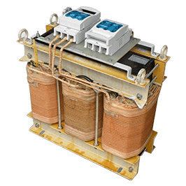
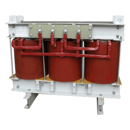
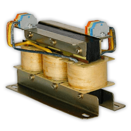
Industrial magnetic manufacturing environment Heavy duty three-phase line and load reactor up to 2500A
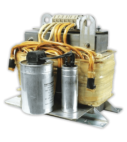
Drive filtering systems High performance sine wave and harmonic filter series
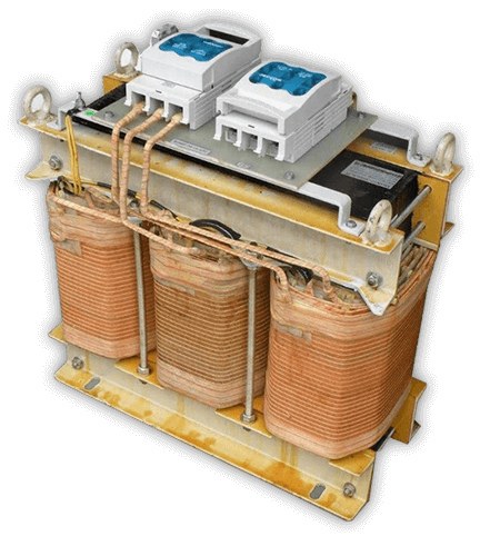
Precision magnetic engineering Industrial isolation transformer for drive systems
0 AMax. Reactor Current Capacity
0+Years Automation Heritage
0 m²Dedicated Plant Infrastructure
0+Tier-1 Global OEMs Served
0 kVAMax. Magnetic System Power
Authoritative Engineering Guide

Why Global Procurement Teams Specify Line and Load Reactors for Mission-Critical VFD Reliability

35%-65%

Reduction in Total Harmonic Current Distortion (THDi) and peak dv/dt voltage transients across automated variable speed drives

In modern industrial automation, Variable Frequency Drives (VFDs) and variable speed drives (VSDs) operate as non-linear electrical loads. While pulse-width modulated (PWM) inverter topologies using high-frequency Insulated Gate Bipolar Transistors (IGBTs) deliver precise torque control and motor velocity management, they inject significant electrical disturbances into the supply grid and subject downstream motor windings to severe dielectric stress. Understanding the dual role of the Line Reactor (input side) and Load Reactor (output side) has become a technical prerequisite for electrical engineering managers, systems integrators, and international procurement specialists.

Manufactured by Prima Transformers Pvt. Ltd. at our state-of-the-art 5,500 m² facility in Santej, Ahmedabad, our heavy-duty three-phase line and load reactors are rated up to 2500A continuous current. Backed by the rich automation engineering pedigree of Prima Automation (India) Pvt. Ltd. established in 1990, every magnetic component is engineered from the ground up to eliminate non-linear drive faults, preserve network power factor, and prevent catastrophic insulation degradation in motors operating worldwide.

  • Mitigates IEEE 519 line harmonic penalties
  • Dampens destructive dv/dt voltage reflections
  • Extends motor bearing lifespan & winding life
  • CE marked with automated factory test logs
Send an Inquiry Explore Manufacturing Roots
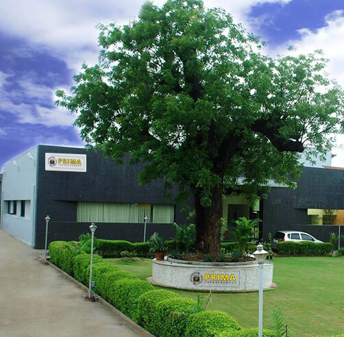
CE Certified Prima Transformers 5,500 m² advanced manufacturing facility in Santej, Ahmedabad
Technical Disambiguation

Line Reactor vs. Load Reactor: Critical System Functions

While both devices utilize precision air-gapped three-phase inductors, their electrical topology, design stresses, and mechanical placement within the drive circuit serve diametrically opposite protective functions.

Line Reactor (Input AC Choke / Drive Front-End)

Installed between the incoming three-phase AC utility feed and the diode bridge rectifier input terminals (L1, L2, L3) of the drive. It introduces controlled inductive reactance (typically 3% or 5% nominal system impedance) ahead of the converter section.

  • Harmonic Current Attenuation: Lowers high-frequency non-linear ripple current drawn by the capacitor-charging cycle, cutting total harmonic current distortion (THDi) from upwards of 80% down to 35% or below, assisting compliance with IEEE 519 and IEC 61000-2-4 standards.
  • Mains Transient Absorption: Serves as an inductive buffer against utility capacitor switching spikes, lightning strike overvoltage, and line notches, safeguarding fragile front-end diodes and SCR semiconductors.
  • Mitigation of Nuisance DC Bus Tripping: Absorbs voltage surges before they reach the drive's intermediate DC link capacitors, eliminating spurious overvoltage fault shutdowns.
  • Short-Circuit Stress Relief: Limits the rate of current rise (di/dt) into the drive during utility system ground faults or sudden short-circuit events.
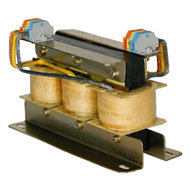
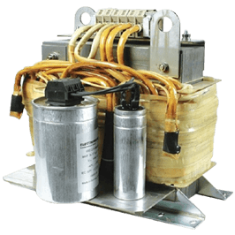
Load Reactor (Output AC Choke / Inverter-Motor Interface)

Positioned immediately between the VFD inverter terminals (U, V, W) and the electric motor terminals. It directly filters the high-frequency pulsed waveforms output by fast-switching IGBT stages.

  • Limiting dv/dt Rate of Voltage Rise: Modern IGBT switches toggle in 50 to 400 nanoseconds, producing voltage rise rates (dv/dt) exceeding 5,000 to 10,000 V/μs. A load reactor slows down the wavefront edge, protecting phase insulation.
  • Standing Wave Reflection Mitigation: Over motor cable runs exceeding 30 to 50 feet, impedance mismatches cause reflected wave phenomena, doubling terminal voltage up to 1600V on 480V networks. The load reactor damps these reflections.
  • Motor Thermal & Acoustic Optimization: Smooths PWM ripple currents, lowering high-frequency eddy current losses inside motor laminations, dropping operating temperature by 10°C to 20°C and dampening audible motor hum.
  • Bearing Protection: Reduces high-frequency parasitic common-mode capacitive currents that cause micro-arcing and bearing fluting.
Selection Engineering

Engineering Selection Matrix: 3% vs. 5% Impedance Calculation

Selecting nominal impedance requires balancing voltage drop against power quality performance and plant short-circuit capacity.

Selection Parameter 3% Nominal Impedance Reactor 5% Nominal Impedance Reactor Engineering Application Note
Harmonic Attenuation (THDi) Reduces THDi to ~35% - 40% Reduces THDi to ~28% - 32% For IEEE 519 point of common coupling (PCC) limits, 5% is preferred for stiff systems.
Fundamental Voltage Drop Approx. 3% at rated motor load Approx. 5% at rated motor load Ensure the drive bus voltage margin permits 5% drop under peak current operation.
Capacitor Switching Transient Immunity High suppression (>80% transient attenuation) Maximum suppression (>95% transient attenuation) Mandatory when power factor correction capacitor banks switch on the same transformer bus.
Recommended Grid Stiff Factor Short-circuit ratio (kVA source / kVA drive) < 20 Short-circuit ratio (kVA source / kVA drive) > 20 If installed directly adjacent to a high-capacity utility transformer, choose 5% impedance.
Recommended Output Cable Run Standard protection: 30 ft to 150 ft (10m - 45m) Extended protection: 150 ft to 300 ft (45m - 90m) For distances > 500 ft (150m), engineer an LC Sine Wave Filter rather than a reactor alone.
Audible Noise & Thermal Dissipation Compact frame, standard convection cooling Slightly larger core window, higher iron mass Class H insulation (180°C) with computerized vacuum-pressure impregnation (VPI).

Formula Reference: Reactance \( X_L = 2\pi f L \). Percentage Impedance \( \%Z = \frac{I_{rated} \cdot \sqrt{3} \cdot X_L}{V_{line-line}} \times 100 \). Prima Transformers calculates winding turns, lamination gap, and heat sink geometry directly against your nominal grid frequency (50 Hz or 60 Hz) and ambient temperatures up to 55°C.

Accelerate Project Turnaround

Need Precision-Engineered Line and Load Reactors for Upcoming Project Panels?

Whether you require standard 3% or 5% chokes or bespoke low-loss magnetic reactors built to custom dimensional footprints, our engineering team delivers design calculations and verified test certifications within 24 hours.

Send an Inquiry
Why Choose Prima Transformers

Engineering Superiority Backed by 35 Years of Automation Legacy

Combining heavy transformer manufacturing capabilities with true control-panel engineering pedigree.

Built by Automation Panel Builders, for Global Automation OEMs

Most transformer companies understand magnetic core winding, but lack operational insight into how reactors interact with VFD microprocessors, servo drives, and industrial PLCs inside cramped electrical cabinets. Prima Transformers Pvt. Ltd., established in 2006, is a 100% subsidiary of Prima Automation (India) Pvt. Ltd., which has engineered complex SCADA systems, hazardous-area pressurized cabinets, and control panels since 1990.

This unique parentage dictates our engineering priorities: high saturation flux margin (preventing inductance collapse during drive start), low audible acoustic noise through specialized epoxy dipping, low harmonic stray losses, and terminal block layouts optimized for straightforward cabinet installation and serviceability.

  • 5,500 m² infrastructure in Santej, Ahmedabad
  • Computerized OC/SC & digital LCR testing
  • Custom current ratings up to 2500 Amperes
  • Full CE compliance for export to EU, Americas & MEA
Quality Assured Prima Transformers production floor and testing panels
Frequently Asked Questions

Key Technical Inquiries from Global Procurement Engineers

Comprehensive answers compiled from international consultant audits, engineering specs, and client procurement dialogues.

What is the primary difference between a line reactor and a load reactor in VFD installations?

A Line Reactor is wired between the AC power supply and the input terminals of the Variable Frequency Drive (VFD). Its primary roles are to suppress input current harmonic distortion (THDi), absorb line surges and transient voltage spikes, reduce nuisance DC bus overvoltage tripping, and protect the front-end bridge rectifier. In contrast, a Load Reactor is installed between the VFD inverter output terminals and the electric motor. It is engineered to smooth high-frequency PWM switching pulses, dampen destructive dv/dt voltage spikes, eliminate standing wave voltage reflections over long cable runs, and mitigate motor insulation breakdown and premature bearing fluting.

When should an engineer specify a 3% impedance reactor versus a 5% impedance reactor?

A 3% impedance reactor provides robust general-purpose drive protection, transient attenuation, and sufficient harmonic mitigation (typically reducing THDi down to 35%-40%) with minimal fundamental voltage drop (~3%). It is ideal for balanced networks with moderate electrical noise. A 5% impedance reactor should be specified when stricter harmonic compliance (approaching IEEE 519 targets) is required, when the drive represents a significant portion of a stiff utility supply with high available fault current (low source impedance), or when mitigating severe cross-talk and nuisance drive tripping caused by power factor capacitor switching on the same substation bus.

At what motor cable length does an output load reactor become technically mandatory?

An output load reactor is technically necessary when motor feed lead lengths exceed 30 to 50 feet (10 to 15 meters) on 400V/480V networks, and becomes critical on 690V systems even at shorter lengths. Modern IGBTs switch in nanoseconds, creating steep wavefronts (dv/dt up to 10 kV/μs). At lead lengths where the pulse travel time matches or exceeds half of the rise time, transmission line impedance mismatch produces reflected waves that can double the peak voltage at motor terminals (up to 1600V or higher), compromising phase-to-phase magnet wire insulation. For cable runs beyond 500 feet (150 meters), a full LC sine wave filter is recommended.

How does core saturation affect reactor performance under harmonic loading?

Standard inductors designed only for 50/60 Hz fundamental current saturate when subjected to high-order harmonic currents. Under saturation, the magnetic core cannot maintain its magnetic flux density (B), causing the inductance value to drop sharply precisely when peak current limiting is needed most. Prima Transformers engineers line and load reactors with precision air-gapped grain-oriented silicon steel cores and high-linearity magnetic designs, ensuring that rated inductance is maintained up to 150% continuous current and 200% short-term overload without core saturation.

What quality certifications and routine factory tests are conducted on Prima reactors?

All line and load reactors manufactured by Prima Transformers are CE marked and compliant with IEC 60076-6 and IEEE standards. Every unit undergoes automated computerized routine factory testing in our 5,500 m² Santej facility, including digital LCR inductance measurement across phases, milli-ohm winding DC resistance balance testing, high-voltage dielectric breakdown (Hi-Pot) testing, double-voltage double-frequency (DVDF) induced overvoltage validation, and temperature-rise verification.

Can Prima customize line and load reactors for non-standard voltages or IP enclosures?

Yes. Beyond standard open-frame IP00 constructions for cabinet mounting, we engineer custom ventilated enclosures rated IP20, IP21, IP23, and up to IP54/IP55 for harsh outdoor or chemical environments. We support system voltages from 208V up to 690V (and medium voltage ranges upon request), 50Hz and 60Hz dual ratings, custom busbar terminal orientations, thermal switch interlocks, and copper or aluminum wound configurations.

Enterprise Validation

Trusted by Global Heavy-Industry Leaders

Our magnetic assemblies and power quality components are deployed across high-demand automation systems and international infrastructure projects.

Continuous Process IndustriesWater & Wastewater TreatmentMetals & Rolling MillsRenewable Energy FarmsMining & ExtractionHVAC & Marine PropulsionControl Panel BuildersDrive OEM System Integrators