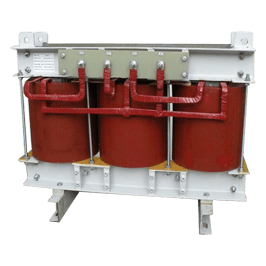
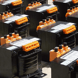
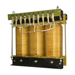
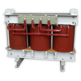
Santej, Ahmedabad, Gujarat, IndiaCE-Marked Transformers for Export
Serving OEMs & Projects Worldwide
CEMarked
0+Years Magnetics Heritage
0 HPMax Filter Capacity
0 m²Modern Production Plant
0 AMax Reactor Rating
0+Global OEMs Supplied
Technical Authority & System Reliability
Motor Protection Filter Engineering: Eliminating VFD Voltage Spikes, dV/dt Stress, and Premature Bearing Failure
25+
Years of specialized manufacturing excellence in magnetic reactors, harmonic mitigation, and automated motor drives
In contemporary industrial drives utilizing high-speed Insulated Gate Bipolar Transistors (IGBTs) with microsecond switching speeds, the severe rise time (dV/dt exceeding 10,000 V/μs) induces destructive electrical phenomena across motor windings. When pulse width modulation (PWM) waveforms encounter impedance mismatches along motor cabling, traveling voltage waves double at motor terminals, perforating inter-turn dielectric insulation and generating capacitively coupled common-mode voltages that spark destructive electrical discharge machining (EDM) pitting inside motor bearings.
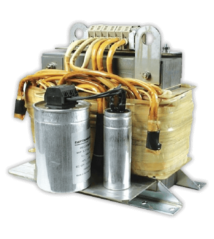
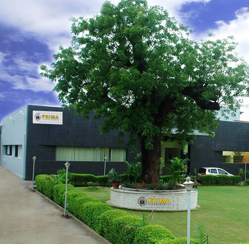
A precision-engineered Motor Protection Filter by Prima Transformers Pvt. Ltd. provides complete electromagnetic attenuation. As an established Indian manufacturer operating a state-of-the-art 5,500 m² facility in Santej, Ahmedabad, we manufacture CE-marked motor protection filters, dV/dt filters, and sine wave conditioning units rated up to 500HP and load reactors up to 2500A. Leveraging our parent company Prima Automation's 35-year control panel heritage since 1990, every solution is built with in-depth knowledge of real-world inverter-motor drive interactions.
Reduces peak line-to-line voltage to <1000V on 400V–690V systems
Eliminates reflected-wave overvoltages on cables exceeding 1,000m
Prevents bearing fluting, electro-erosion, and premature grease degradation
Extends operational lifespan of standard IEC & NEMA motors
Motor Protection Filter Recommendations: Matching Topologies to Cable Architecture
Selecting the optimal output protection topology depends on cable lengths, drive switching frequencies, motor insulation ratings (IEC 60034-17 vs. IEC 60034-25), and acoustic restrictions.
AC Load Reactors (3% – 5%)
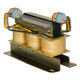
Cable Distance: Up to 30 meters. Protection Scope: Acts as an essential first-stage line choke. Moderates dV/dt from >10,000 V/μs down to approximately 1,000 V/μs. Protects drive output transistors from short-circuit capacitive charging currents and dampens minor switching ringings in compact factory floors.
Advanced dV/dt Snubber Filters
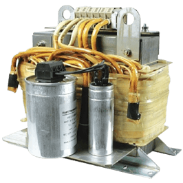
Cable Distance: 30 to 150 meters. Protection Scope: Integrates a tuned inductor with an RC clamping network. Limits dV/dt to <500 V/μs and curbs terminal voltage spikes below 135% of DC bus voltage. Prevents dielectric breakdown in general-purpose motor stators without adding excessive footprint or capacitive line losses.
Full Sine Wave Output Filters
Cable Distance: 150 meters to over 1,500 meters. Protection Scope: Low-pass LC matrix with cut-off frequency placed below drive switching frequency. Smooths PWM pulses into pure sinusoidal line-to-line voltages. Completely eliminates reflected wave surges, acoustic motor whining, and common stray capacitive leakages for deep well pumps and mine hoists.
Core Magnetics Catalog
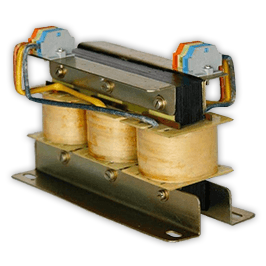
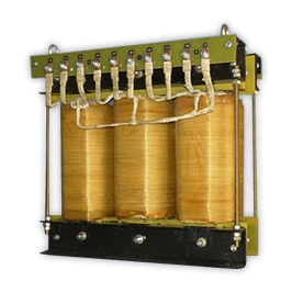
Motor Protection & Drive Magnetics Manufactured In-House
Manufactured using high-grade grain-oriented silicon steel (CRGO), Class H copper conductors, and vacuum pressure impregnation (VPI).
A technical guide for project procurement leads to evaluate performance trade-offs against installation constraints.
Filter Topology
Max Recommended Cable
Peak Voltage Reduction (Vpk)
Typical dV/dt Suppression
Bearing Current Attenuation
Audible Noise Mitigation
Standard AC Load Reactor (3% - 5%)
≤ 30 Meters (Unshielded)
10% - 20% Reduction
< 1,000 V/μs
Low (Minimal Common Mode effect)
None
Standard dV/dt Filter
Up to 150 Meters
Capped at < 135% DC link voltage
< 200 - 500 V/μs
Moderate (Reduces discharge rise speed)
Slight damping
Sine Wave Output Filter
Up to 1,500+ Meters
100% elimination of spikes (< 1.05 × Vnom)
Converts to smooth sinusoidal wave
High (Eliminates high-frequency EDM)
Complete elimination of motor hum
Sine Wave Filter + Common Mode Choke
Submersible & Long Run (>2,000m)
Pure Sine Line-to-Line & Line-to-Ground
Near-linear 50/60Hz profile
Maximum (Nullifies circular shaft voltage)
Silent motor operation
*Note: Specifications adhere to IEC 60034-17 / IEC 60034-25 standards. Customized thermal dissipation ratings and low-inductance packaging available upon engineering consultation.
Technical Physics & Physics of Failure
Why Variable Frequency Drives Destroy Electric Motors Without Protection
Understanding the electrical phenomenon behind insulation puncture and electro-discharge bearing destruction.
Transmission Line Reflections & Standing Waves
Modern inverter drives utilize silicon IGBT or wide-bandgap SiC semiconductor devices that switch DC bus voltage in 50 to 200 nanoseconds. The pulse propagation velocity along standard industrial motor cables is roughly 150 meters per microsecond. Because an un-terminated motor terminal acts as a high-impedance open circuit relative to cable surge impedance (typically 75–120 Ω), the traveling wave reflects back with identical phase polarity.
This reflection doubles voltage amplitudes up to 2.0 to 2.5 times the nominal DC bus voltage (often exceeding 1,600V to 2,000V on a 480V/690V line). These severe peaks concentrate on the first few turns of the stator phase winding, exceeding the dielectric breakdown rating of standard enamel wire, sparking partial discharge (corona), and destroying stator coils.
Common-Mode Voltage & Bearing Fluting (EDM)
Three-phase sinusoidal power sums vectorially to zero. However, three-phase PWM switching generates a non-zero neutral voltage termed common-mode voltage (CMV). This rapidly pulsed CMV capacitively couples from the stator to the motor rotor shaft across the air gap. When rotor voltage exceeds the dielectric breakdown threshold of the thin oil or grease lubricant film separating bearing rolling elements from their raceways, an arc discharge strikes.
This electrical discharge machining (EDM) current vaporizes minute microscopic steel craters. Over running hours, repetitive arcing produces a washboard pattern termed "fluting", accelerating mechanical vibration, acoustic screaming, lubrication carbonization, and eventual catastrophic bearing seizure.
Future Market Analysis
Market Shifts: Procurement & Technology Trends in Motor Protection Filters
How global electrification, Wide Bandgap (WBG) power electronics, and total lifecycle accountability are redefining procurement standards.
Wide Bandgap (SiC/GaN) Fast Switching
As variable speed drives adopt Silicon Carbide (SiC) and Gallium Nitride (GaN) switching bridges, switching frequencies reach upwards of 20kHz to 100kHz with nanosecond edge transitions (dV/dt > 50,000 V/μs). Standard reactors overheat due to core hysteretic losses. The future belongs to advanced motor protection filters utilizing ultra-low-loss nanocrystalline or specialized powder-core alloys engineered for extreme harmonic frequencies.
Decentralized & Subsea Offshore Pumping
Global procurement teams in deep-sea offshore oil recovery, high-temperature geothermal wells, and municipal deep groundwater extraction encounter single cable runs extending past 1,000 to 3,000 meters. These systems prohibit drive-to-motor short-run topologies. Global plant operators are universally specifying integrated Sine Wave Filters to prevent cable insulation capacitance puncture and to ensure equipment longevity without costly crane pullouts.
Lifecycle Efficiency & Retrofit Standards
Total Cost of Ownership (TCO) models are replacing initial capex purchasing models. Installing a precision-engineered motor protection filter is now standard insurance against premature rewind costs ($10,000–$50,000 per critical motor) and unbudgeted manufacturing shutdown lines. Furthermore, filtering permits legacy non-inverter-duty motors to run safely on newer high-efficiency VFD controls without stator replacement.
Engineered For Zero Motor Downtime
Safeguard Your Critical Drive Motors With Certified Filtering Magnetics
Whether you require standard 500HP sine wave filters for long cable runs or tailored dV/dt snubber assemblies for OEM control skids, our application engineers provide turnkey sizing, thermal analysis, and CE-compliant documentation.
Why International OEMs Partner with Prima Transformers
Combining 25+ years of transformer engineering, certified export quality, and integrated electrical automation experience.
Unmatched 5,500 m² Advanced Manufacturing Facility
Located in the industrial corridor of Santej, Ahmedabad, Prima Transformers Pvt. Ltd. operates one of the most comprehensive dedicated magnetic production facilities in western India. As an ISO-compliant, CE-certified organization and a 100% subsidiary of Prima Automation (India) Pvt. Ltd. (founded 1990), we bridge the gap between high-capacity automated winding and demanding control panel integration.
Every motor protection filter, harmonic reactor, and dry-type transformer undergoes stringent routine testing in our computerized test bays prior to worldwide dispatch. Our parent company's 35 years in PLC, SCADA, and hazardous-area pressurized panel engineering ensures that our filters integrate seamlessly into control cabinets, meeting tight thermal clearance, low audible noise, and precise electromagnetic compatibility (EMC) regulations.
Double Voltage Double Frequency (DVDF) Induced Testing
Precision Digital LCR & Milli-ohm Winding Resistance Meters
Infrared Thermal Imaging for Verification of Temperature Rise
Global Track Record
Trusted by Industrial Titans Worldwide
From cement mills and offshore platforms to steel rolling and automation OEMs, our magnetics ensure uninterrupted uptime.
Submersible PumpsOil & Gas ExtractionSteel & Wire MillsCement & Heavy MiningChemical Processing PlantsRenewable Energy FacilitiesOEM Machine BuildersWater & Wastewater Treatment
Procurement Intelligence
Frequently Asked Questions: Motor Protection Filter Engineering & Sizing
Direct technical answers to questions commonly queried by electrical contractors, MEP consultants, and global procurement leads.
What exact electrical problems does a Motor Protection Filter solve?
A motor protection filter mitigates destructive high dV/dt voltage pulses, eliminates reflected transmission line wave amplification at the motor terminals, attenuates common-mode voltages, and prevents electrical discharge machining (EDM) fluting across bearing raceways caused by IGBT PWM switching. It also eliminates high-frequency stator winding heating and cancels acoustic motor whining caused by drive carrier frequencies.
When should I specify a dV/dt filter versus a Sine Wave Filter?
Specify a dV/dt filter when motor cable lengths range between 30 and 150 meters and the primary objective is capping peak voltage below 135% of the DC bus and reducing dV/dt to <500 V/μs for inverter-duty motors. Specify a full Sine Wave Filter when cable runs exceed 150 meters (up to 1,500m+), for older non-inverter-duty motor retrofits, in submersible deep-well pumping, when driving step-up transformers from drive outputs, or where acoustic silence is mandatory.
Can a motor protection filter cause voltage drop across the motor terminals?
A properly designed reactor or dV/dt filter typically introduces a nominal voltage drop of only 1% to 3% at rated fundamental frequency (50/60Hz). A sine wave filter generally induces a fundamental voltage drop between 5% and 8% under full load. In variable-torque centrifugal pump and fan loads, this drop is negligible, while for constant-torque critical loads, minor inverter output parameter adjustment (V/f boost) easily compensates for this marginal impedance drop.
Are Prima Transformers motor protection filters compatible with multi-motor setups on a single drive?
Yes. When multiple motors run in parallel from a single variable frequency inverter, total cumulative cable lengths escalate dramatically, triggering dangerous cumulative high-frequency capacitive ground leakage currents. Installing a centralized Sine Wave Motor Protection Filter at the drive output stabilizes the entire branched network into a pure sinusoidal sinusoidal grid, eliminating spurious overcurrent drive tripping and protecting all parallel motors simultaneously.
What details are required to receive a fast, customized quotation?
Please provide the motor rated power (HP/kW) and full load amp (FLA), nominal line voltage (e.g., 400V, 480V, 690V), fundamental operating frequency (50/60Hz), maximum drive switching frequency (kHz), cable length and shielding type, motor insulation standard (IEC 60034-17 / IEC 60034-25), and desired enclosure protection rating (open chassis IP00, IP20, or outdoor IP54/55).