
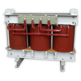
0+Years Automation Heritage
0+Global OEMs Supplied
0 m²State-of-the-Art Plant Area
0 kVAMax Magnetics Capability
0%Computerized Routine Tested
Next-Generation Grid Monitoring
How Are Modern Instrument Transformers Selected, Engineered, and Verified for High-Reliability Electrical Systems?
25+
Years of specialized magnetics manufacturing supported by a 35-year control automation lineage
In electrical power networks, switchgear assemblies, and automated industrial substations, an Instrument Transformer serves as the fundamental sensory interface. By converting extreme primary currents and primary voltages into standardized, galvano-isolated secondary levels (typically 1A, 5A, 100V, or 110V), these precision electromagnetic units enable revenue-grade metering, real-time power quality profiling, and high-speed protective relaying.
Engineered at Prima Transformers' specialized 5,500 m² facility in Santej, Ahmedabad, our instrument transformers are built to resolve critical real-world challenges: eliminating ratio phase displacement under varying power factors, mitigating high saturation during sudden short-circuit transient faults, and maintaining thermal stability under harsh ambient environments. Backed by our parent company Prima Automation (India) Pvt. Ltd.'s legacy since 1990 in industrial SCADA, PLC, and hazardous-area panel construction, we engineer each instrument transformer with deep empirical knowledge of panel space limitations, electromagnetic compatibility (EMC), and robust terminal isolation.
- Strict adherence to IEC 61869-1/-2/-3 & IEEE C57.13
- CE-Marked units engineered for global OEM export
- High-grade cold-rolled grain-oriented (CRGO) magnetic cores
- Automated computerized test reports supplied with every dispatch
Quality Assured 
Engineered Product Portfolio
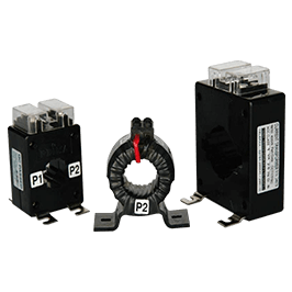
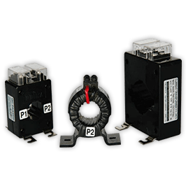
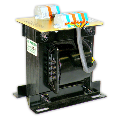
Recommended Instrument & Magnetics Solutions
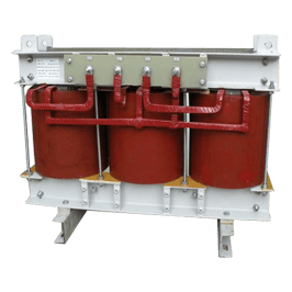
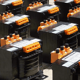
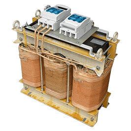
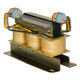
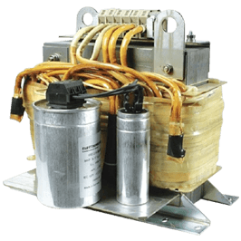
Designed for seamless mechanical and electrical integration into motor control centers (MCC), power control centers (PCC), GIS/AIS switchgear, and utility grid interfaces.
Market Intelligence
Strategic Procurement & Sourcing Trends in Instrument Transformers
How supply chain executives, utility project managers, and switchgear OEMs are shifting specifications for resilience, decarbonization, and digitized operations.
Supply Chain Regionalization & Western Compliance
International procurement authorities across North America, Europe, and the Middle East are actively diversifying magnetic component sources away from single-country dependency. However, procurement teams require manufacturers with established international credentials, such as CE marking and verified adherence to IEC 61869 / IEEE C57.13 standards.
Buyers now heavily weigh vendor track records, transparent raw material provenance (including high-grade CRGO electrical steel and certified copper conductors), and complete traceable routine testing to satisfy stringent public infrastructure audits.
Transition to Cast Resin & Dry-Type Safety
Environmental, Social, and Governance (ESG) mandates have accelerated the phase-out of mineral-oil-insulated instrument transformers in medium-voltage indoor substations and industrial facilities. Procurement directives mandate non-flammable, self-extinguishing epoxy cast resin dry-type transformers.
Eliminating dielectric oil prevents hazardous leakage into soil and removes the explosive risk associated with internal arcing faults, resulting in lower insurance premiums and substantially reduced life-cycle maintenance costs for end-users.
Renewable Energy & Bi-Directional Power Dynamics
With widespread integration of solar PV inverters, wind turbine converters, and battery energy storage systems (BESS), modern grids exhibit high harmonic distortions and bi-directional power flows. Buyers are requesting customized instrument transformers rated for non-sinusoidal waveforms.
Standard metering units easily saturate or suffer severe thermal derating in harmonic-rich environments; hence, procurement engineers specify expanded linear dynamic ranges and thermal Class H/F insulation systems capable of enduring continuous inverter ripple.
Total Cost of Ownership (TCO) vs Capital Outlay
Sourcing teams are moving past simple lowest-unit-cost metrics toward comprehensive TCO calculations. A substandard instrument transformer that drifts out of its calibration class leads to compounding revenue metering discrepancies or disastrous relay failure during a busbar fault.
Purchasers prioritize precision winding geometry, low excitation losses, high mechanical short-circuit withstand, and computerized calibration documentation that eliminates commissioning delays and avoids catastrophic substation downtime.
Technological Horizon
Future Development Trends: The Evolution of Instrument Transformers
Key engineering innovations reshaping sensory magnetics for the next era of smart power grids and Industry 4.0.

LPITs & IEC 61850 Process Bus
The modernization of substations centers on Low-Power Instrument Transformers (LPITs) and optical/Rogowski sensor configurations interfacing directly with Merging Units. By transmitting digitized Sampled Values (SV) via optical fiber under IEC 61850-9-2LE, substations eliminate hundreds of copper hardwires, reduce footprint, and eradicate secondary open-circuit hazards.

Nanocrystalline & Amorphous Magnetic Cores
To satisfy Class 0.2S and Class 0.1 metering precision across extreme current variations (1% to 120%), advanced metallurgical cores made of ultra-thin nanocrystalline ribbons are displacing traditional silicon steel. They offer exceptionally high initial magnetic permeability, near-zero coercive force, and minimal hysteresis loss, keeping instrumentation accurate even at ultra-low loads.

Embedded IoT & Condition Analytics
Instrument transformers are transforming from passive electromagnetic sensors into intelligent grid nodes. Next-generation medium and high-voltage units integrate embedded fiber-optic temperature probes, dielectric partial discharge (PD) micro-sensors, and capacitive leakage monitoring, feeding continuous data into predictive asset maintenance algorithms.
Engineering Matrix
Technical Comparison: Metering vs Protection Instrument Transformers
Critical electrical performance parameters evaluated during engineering design and switchgear selection.
| Design Parameter | Metering Current Transformers (CT) | Protection Current Transformers (CT) | Voltage / Potential Transformers (VT/PT) |
|---|---|---|---|
| Primary Functional Goal | Precise energy billing, power factor calculation, and SCADA monitoring | Accurate fault current detection to trigger protective trip relays | Step-down busbar voltage for meters, synchroscopes, and protective relays |
| Standard Accuracy Classes | 0.1, 0.2, 0.2S, 0.5, 0.5S (IEC 61869-2) / 0.3, 0.6 (IEEE C57.13) | 5P10, 5P20, 10P10, 10P20, Class PS / Class X | 0.1, 0.2, 0.5, 3.0, 3P, 6P |
| Core Magnetic Saturation Point | Low Saturation: Intentionally saturates at 1.2x to 1.5x rated current (ISF < 5 or < 10) | High Saturation Knee Point: Remains strictly linear up to 10x, 20x, or 30x rated fault current (ALF ≥ 10/20) | Linear overvoltage operation up to 1.2x continuous, and 1.5x or 1.9x rated for 30s during earth faults |
| Typical Rated Burden | 2.5 VA, 5 VA, 10 VA, 15 VA (matched to modern digital solid-state meter impedance) | 10 VA, 15 VA, 30 VA, 50 VA (engineered to account for lead wire resistance and relay burden) | 10 VA to 200 VA (depending on instrumentation and auxiliary control requirements) |
| Core Material Selection | High-permeability Nanocrystalline, Permalloy, or low-loss HiB CRGO steel | Grain-Oriented Silicon Steel (CRGO) with large cross-sectional area to withstand fault flux | Low-loss cold-rolled grain-oriented silicon steel with precision wound layer insulation |
| Secondary Open-Circuit Vulnerability | Extreme: Extreme flux density causing dangerous kilovolt peak arcs and destruction | Extreme: High voltage hazard requiring dedicated shorting terminal blocks | Vulnerable to short circuits: Must be protected by secondary HRC fuses or miniature breakers |
Prima Transformers custom-engineers multi-core units combining dedicated Metering and Protection windings within a single compact cast-resin or tape-insulated housing to maximize switchgear compartment efficiency.
Advanced Indian Manufacturing Hub
5,500 m² World-Class Facility in Santej, Ahmedabad
From high-tension precision winding machines to fully automated computerized test chambers, Prima Transformers maintains total quality control over every stage of magnetic engineering.
Comprehensive In-House Routine & Type Testing Equipment
- Automatic computerized transformer test benches for ratio error and phase displacement
- Dedicated current transformer excitation curve and knee-point voltage (Vk) testing panel
- Double Voltage Double Frequency (DVDF) induced high-voltage withstand testing apparatus
- Multi-kV insulation resistance testers (automated digital Megger systems)
- Computerized open-circuit and short-circuit (OC/SC) loss parameter analyzers
- Calibrated digital milli-ohm meters for four-wire precision winding resistance measurement
- High-precision digital LCR meters for leakage inductance and parasitic capacitance screening
- Multi-channel infrared thermographic scanners for accurate thermal-rise verification
Why Switchgear Builders Choose Prima
Enterprise Advantage: 35 Years of Industrial Automation Synergy
Prima Transformers Pvt. Ltd. was incorporated in 2006 as a 100% subsidiary of Prima Automation (India) Pvt. Ltd., an industry leader that has specialized in engineering custom PC, PLC, and SCADA-integrated control panels, hazardous-area flameproof systems, and complex drive enclosures since 1990.
This distinct systems-integrator heritage gives our magnetic engineering team an unparalleled advantage that standalone coil winders simply lack:
- Panel-Builder Perspective: We understand the spatial and mechanical constraints inside compact switchgear, providing optimized terminal layouts and vibration-proof mountings.
- EMC & Harmonics Expertise: Drawing on decades of variable-speed drive experience, we engineer instrument transformers that resist electromagnetic noise and high harmonic distortion.
- Hazardous & Extreme Environment Readiness: Proven engineering capability for petrochemical, marine, mining, and metallurgy operating under extreme ambient conditions.
- CE-Marked International Quality: Built to meet export documentation standards, guaranteeing rapid customs clearance and immediate project acceptance across global jurisdictions.
Validated by Tier-1 Enterprises
Trusted by Global Industry Leaders
Our transformers and reactors safeguard critical processes in multinational infrastructure, heavy manufacturing, and energy utilities.















Substation Switchgear (AIS & GIS)Solar & Wind Farm InterconnectionsHeavy Metallurgy & Arc FurnacesContinuous Process Chemical PlantsOil & Gas RefineriesHyperscale Data Center DistributionMarine & Offshore Switchboards
Procurement & Technical Clarifications
Frequently Asked Questions by Global Buyers
Clear, engineering-backed answers to the technical questions most frequently raised during tender submissions and equipment selection.
What is the core functional difference between a Metering CT and a Protection CT?
The distinction lies in their magnetic saturation characteristics under normal versus abnormal current conditions:
Metering Current Transformers (CTs) demand supreme accuracy (e.g., Class 0.2, 0.2S, 0.5) over a standard operating band from 10% to 120% of rated nominal current. They are purposefully engineered with a small magnetic core that saturates quickly (Instrument Security Factor, ISF < 5 or < 10) during line fault conditions. This saturation protects delicate energy meters and telemetry equipment connected to the secondary winding from destruction during huge primary overcurrent surges.
Protection Current Transformers (CTs) (e.g., Class 5P10, 5P20, Class PS) must reproduce severe primary fault currents with high fidelity without saturating. With an Accuracy Limit Factor (ALF) of 10, 20, or higher, their significantly larger magnetic cores remain completely linear up to 10 to 20 times nominal rating, enabling protective relays to instantly determine the fault type and magnitude to trigger circuit breaker isolation.
Why is opening the secondary circuit of an energized current transformer potentially fatal?
Under normal energized operation, the primary current's magnetomotive force ($N_p \times I_p$) is nearly balanced and neutralized by the opposing demagnetizing ampere-turns of the closed secondary circuit ($N_s \times I_s$), leaving only a tiny resultant magnetizing current to establish magnetic core flux.
If the secondary circuit is opened while primary load flows, the opposing secondary ampere-turns drop instantly to zero. The entire uncountered primary ampere-turns act as pure excitation magnetizing force, driving the core deep into extreme magnetic saturation. As the primary sinusoidal alternating wave rapidly transitions through zero, the flux change ($d\Phi/dt$) induces massive, peak voltage spikes ranging from several thousand volts up to tens of kilovolts across the open secondary terminals. This presents a lethal shock hazard to technicians, breaks down winding insulation, and causes severe core overheating that ruins the transformer.
How does secondary burden affect accuracy, and how do you calculate it?
The total secondary burden represents the total apparent power (in Volt-Amperes, VA) or load impedance (in Ohms, $\Omega$) connected across the secondary terminals at rated secondary current. It equals the vector sum of the internal impedance of all connected instruments (meters, relays), the terminal contact resistances, and the two-way loop resistance of the copper wiring connecting the CT to the instrumentation panel:
$Z_{burden} = Z_{instrument} + R_{lead\_loop} + R_{contact}$
If the actual connected burden exceeds the rated burden marked on the nameplate, the excitation voltage required to drive secondary current increases, causing higher exciting current losses and leading to severe ratio errors and phase displacement outside the certified accuracy class. Modern digital meters draw very little power (often < 0.5 VA), making the resistance of long secondary lead wires the dominant burden component that must be calculated before specifying the VA rating.
What international testing certificates and standards do Prima Transformers comply with?
Prima Transformers designs and manufactures instrument transformers in strict compliance with globally recognized international standards, including:
• IEC 61869-1 & IEC 61869-2 (General requirements & specific requirements for current transformers)
• IEC 61869-3 (Specific requirements for inductive voltage transformers)
• IEEE C57.13 / ANSI (Standard requirements for instrument transformers)
• CE Marking for full compliance with the European Low Voltage Directive (LVD) and relevant industrial health, safety, and environmental regulations.
Every single manufactured unit is tested in our computerized testing facility in Ahmedabad, and full certified routine test certificates (including ratio error, phase displacement, excitation curve, polarity, and insulation dielectric withstand) are provided with every export consignment.
What technical specifications should be provided to receive an accurate, rapid quotation?
To enable our engineering team to design the optimal magnetic solution and generate a fast commercial proposal, please include the following parameters:
1. Type: Current Transformer (CT) or Potential/Voltage Transformer (PT/VT).
2. Transformation Ratio: e.g., 200/5A, 1000/1A, 11000/110V, or multi-ratio taps.
3. Application Class: Metering (Class 0.2, 0.2S, 0.5) or Protection (Class 5P10, 5P20, PS).
4. Rated Burden: VA rating (e.g., 2.5VA, 5VA, 15VA, 30VA).
5. System Voltage & Insulation Level: Rated kV, Basic Insulation Level (BIL).
6. System Frequency: 50 Hz, 60 Hz, or wide-frequency inverter duty.
7. Construction Style: Ring-type (window/toroidal), wound primary, busbar type, or epoxy resin cast.
8. Physical Constraints: Window diameter, maximum external dimensions, terminal orientation, and ambient environmental conditions.
Ready to Build Your Custom Magnetic Solution?
Consult with Our Application Engineering Specialists
Partner with an established manufacturer with over 25 years of specialized transformer expertise and 35 years of industrial control automation excellence. Fast engineering support, custom prototyping, and full CE documentation.