Santej, Ahmedabad, Gujarat, IndiaCE-Marked Transformers for Export
Serving OEMs & Projects Worldwide
CEMarked
0+Years Magnetics Heritage
0 HPMax Sine Filter Rating
< 0%Total Harmonic THDv
0 mCable Length Range
0 m²Testing & Winding Facility
Power Quality Engineering & Motor Longevity
Sine Wave Filter Architecture: Eliminating VFD dv/dt Voltage Stress, Motor Heat, & Long-Cable Peak Reflections
500HP
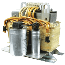
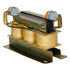
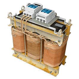
Custom-engineered low-pass LC sine wave filters transforming pulse-width-modulated (PWM) drive output into pure sinusoidal waveforms.
Modern industrial automation relies extensively on Variable Frequency Drives (VFDs) featuring fast-switching Insulated Gate Bipolar Transistors (IGBTs). While these high carrier frequencies (2 kHz to 16 kHz) maximize motor torque efficiency, their extremely steep voltage rise times (dv/dt exceeding 10,000 V/μs) introduce destructive transmission line reflections. When output cables surpass 50 meters, reflected wave phenomena create peak voltages over 200% of DC bus voltage, causing rapid winding inter-turn dielectric breakdown, bearing fluting from electrical discharge machining (EDM), and high audible motor whine.
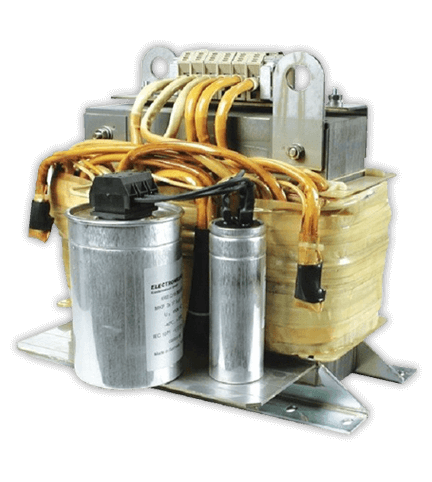
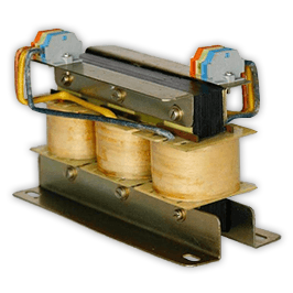
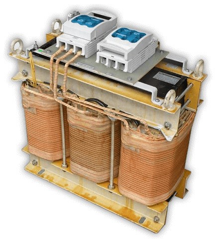
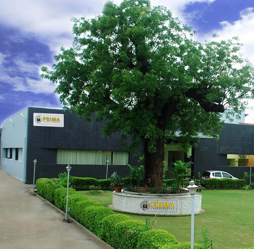
Manufactured by Prima Transformers Pvt. Ltd. in our state-of-the-art 5,500 m² plant in Santej, Ahmedabad, our heavy-duty industrial Sine Wave Filter series functions as a low-pass LC filter network. It completely smooths line-to-line pulse voltages, restricts output voltage total harmonic distortion (THDv) to below 5%, eliminates high-frequency cable charging losses, and enables maintenance-free operation across cable lengths reaching beyond 1,500 meters.
Converts PWM into true sinusoidal voltage (<5% THDv)
Line/Load Reactor vs. dv/dt Filter vs. Sine Wave Filter
Selecting the exact filter topology is essential for system efficiency, investment ROI, and motor thermal protection. Here is how modern output filters compare across critical operational parameters.
Engineering Metric
Standard Load Reactor (AC Inductor)
dv/dt Filter (Choke + Resistor Network)
Sine Wave Filter (Precision LC Network)
Primary Function
Buffers drive IGBTs and reduces short circuit rise times
Slows voltage rise rate to <1,000 V/μs to curb surge peaks
Reconstructs smooth phase-to-phase sine wave; eliminates PWM carrier
Waveform Output
Pulsed PWM with softened wavefront slopes
Clipped PWM pulses with dampened ringing oscillations
Clean sinusoidal voltage (<5% Total Harmonic Distortion)
Maximum Cable Length
30 m to 50 m (unshielded/shielded)
100 m to 300 m max
1,000 m to 1,500 m+ (Ideal for submersibles & remote motors)
Motor Dielectric Stress
Moderate; insulation must meet IEC 60034-25 Part A/B
Good; restricts phase-to-phase peaks to <135% of DC bus
Negligible; perfectly safe for standard, non-inverter-duty motors
Motor Acoustic Noise & Eddy Heat
Noticeable audible switching whistle and core losses
Slight reduction in high-frequency eddy losses
Eliminates high-frequency PWM audible hum and cuts motor thermals by 20-30%
Step-Up Transformer Compatibility
Not recommended (causes insulation puncture and high core saturation)
Risky (high-frequency spikes still trigger localized heating)
Fully compatible; permits direct stepping up via standard distribution transformers
Procurement & Technology Trends in Sine Wave Filters (2025–2030)
As global industrial infrastructure transitions toward deep electrification, renewable microgrids, and high-efficiency motor standards (IE4/IE5), sine wave filter procurement criteria are shifting dramatically.
Wide-Bandgap (SiC/GaN) Switching
The rise of Silicon Carbide (SiC) power semiconductor drives operating at 20 kHz to 50 kHz creates unprecedented dv/dt rates. Modern buyers now demand sine wave filter chokes utilizing low-loss nanocrystalline or high-flux amorphous cores designed to prevent thermal runaway under ultra-high carrier frequencies.
Deep Submersible ESP & Remote Drives
Subsea drilling, deep-well Electrical Submersible Pumps (ESP), and geothermal extraction require cable runs spanning 1,500m to 3,500m. Global EPC contractors now standardize on sine wave filters coupled with step-up transformers at the VFD output, avoiding specialized, ultra-expensive inverter-duty cabling.
IE4 / IE5 Motor Retrofit Protection
Industrial sustainability mandates are forcing plants to retrofit legacy across-the-line motors with variable speed drives. Rather than replacing expensive motors with inverter-rated units, procurement teams deploy sine wave filters, cutting capital expenditure by up to 60% while shielding older stator windings.
Fast Engineering Support
Resolve Inverter Cable Reflections and Motor Overheating
Partner with an engineering-first manufacturer. We calculate your exact LC tuning frequencies, damping resistance, and dissipation curves based on motor cable length and drive switching frequency.
Built upon 35+ years of automation panel building and magnetic engineering expertise.
Panel-Builder DNA Engineered into Every Filter
Prima Transformers Pvt. Ltd. was incorporated in 2006 as a 100% subsidiary of Prima Automation (India) Pvt. Ltd., which has engineered advanced PC, PLC, and SCADA-based control panels since 1990—including flameproof, pressurized, and intrinsically safe panels for hazardous areas.
Because of this rich panel-builder background, we understand the real-world operational challenges of cabinet thermals, magnetic flux leakages, terminal routing, and nuisance drive tripping. We design our sine wave filters with:
Class H (180°C) and Class C (200°C) copper winding configurations
Low-loss high-grade CRGO laminations with precision air gaps
Spanning 5,500 m² in Santej, Ahmedabad, Prima Transformers operates dedicated production bays equipped with automated foil and wire winding machinery, vacuum pressure impregnation (VPI) autoclaves, and comprehensive computerized testing benches.
High-voltage breakdown dielectric withstand testing up to 5 kV
Global Buyer Intelligence
Frequently Asked Questions: Sine Wave Filter Procurement
In-depth technical answers addressing the real questions raised by electrical consultants, EPC directors, and OEM procurement managers.
What is the technical operational difference between a load reactor, a dv/dt filter, and a sine wave filter?
A standard load reactor is a pure series inductor that softens pulse edges slightly and handles modest cable lengths (typically under 30-50m). A dv/dt filter combines a choke with a resistor-damping network to attenuate peak voltage rise times below 1,000 V/μs for cable lengths up to 150-300m. In contrast, an engineered Sine Wave Filter is an LC low-pass filter whose resonant frequency is tuned lower than the inverter carrier frequency. It strips away all high-frequency PWM harmonics, outputting a smooth phase-to-phase sine wave with total harmonic distortion (THDv) below 5%. This permits motor cable runs exceeding 1,000m to 1,500m, completely eliminates voltage reflections, and suppresses motor bearing EDM discharges.
Can installing a sine wave filter eliminate electrical bearing fluting and shaft currents?
Standard differential-mode sine wave filters convert line-to-line PWM voltages into smooth sinusoidal waves, removing circular high-frequency bearing currents induced by line-to-line dv/dt transients. However, common-mode voltages (voltage between the three phases and earth) may still persist. For complete mitigation of shaft grounding voltages in critical large-frame motors (above 100 kW), Prima provides integrated common-mode choke options or recommends pairing with an insulated non-drive-end bearing and shaft grounding brush ring.
What carrier (switching) frequency is required for proper sine wave filter operation?
Sine wave filters rely on a tuned LC resonant frequency positioned safely above the fundamental drive output frequency (50 Hz or 60 Hz) and well below the VFD carrier frequency. Most industrial sine wave filters require a minimum switching frequency of 2 kHz to 4 kHz. Operating the drive below the rated minimum carrier frequency can cause dangerous resonance, overheating the filter capacitors and reactor core. Prima engineers verify drive modulation limits prior to coil fabrication to ensure non-saturating reliability across your operating spectrum (up to 16 kHz).
How does a sine wave filter enable stepping up drive voltage with standard transformers?
Feeding raw PWM pulses directly into a conventional power transformer creates extreme eddy current losses, localized hotspot dielectric puncturing, and catastrophic core saturation due to the sharp dv/dt edges. When a Prima Sine Wave Filter is installed right at the drive output, the transformer receives a clean sinusoidal voltage waveform. This allows OEMs to use standard, off-the-shelf step-up distribution transformers to transmit power at high voltage (e.g., 3.3 kV, 6.6 kV, or 11 kV) down deep boreholes or over long overland cables to submersible pumps and remote mining equipment.
What are the critical parameters required to request a custom sine wave filter quotation?
To deliver an optimized design, our engineering team requires: (1) Drive nominal output voltage and current rating (HP / kW / Amps), (2) Fundamental output frequency range (e.g., 0-50/60 Hz or high-speed up to 400 Hz), (3) Minimum and maximum drive switching frequency (kHz), (4) Total motor cable run distance and cable shielding type, (5) Enclosure requirements (IP00 panel open chassis, IP20 indoor, or IP54 outdoor ventilated), and (6) Ambient operating temperature profile.