Santej, Ahmedabad, Gujarat, India CE-Marked Transformers for Export
Serving OEMs & Projects Worldwide

Auto Transformer

Engineering Architecture

Compact, High-Efficiency Single-Winding Voltage Conversion

An auto transformer is a specialized, highly efficient electromagnetic transformer comprising a single continuous winding, wherein a predetermined section is shared jointly between the primary (input) and secondary (output) circuits. Electrical current in the high-voltage circuit traverses both the series and common winding segments, while the low-voltage current circulates through the common winding portion, adding vectorially to define total common current density.

Because the primary and secondary stages share a significant portion of the active copper conductor and magnetic core, an auto transformer offers marked engineering advantages over conventional two-winding isolation transformers: significantly smaller structural mass, reduced overall physical footprint, lower core-excitation losses, and electrical efficiencies ranging up to 99%.

Auto transformers represent the optimal, cost-effective choice for industrial installations where complete galvanic isolation is not mandated, specifically where the primary-to-secondary ratio (V2:V1) is 0.3 or higher.

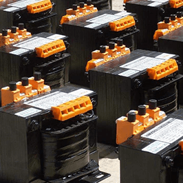
Industrial Three-Phase Auto Transformer engineered by Prima Transformers
Design Ratings

Standard & Custom Technical Specifications

Manufactured and verified in strict accordance with international standards IEC 61558-2-13, IEC 60076, IS 2026, and IS 11171.

Rated Output Capacity 0.5 kVA to 5000 kVA
Operating Voltage Range Primary / Secondary up to 750V
Rated System Frequency 50 Hz / 60 Hz
Vector Group Configuration Yn0 (Three-Phase Wye with Neutral)
Thermal Insulation Class Class F (155°C) / Class H (180°C)
Operating Ambient Temp Up to 50°C Rated Continuous
Full-Load Efficiency 90% to 99% (Model Dependent)
Ingress Protection (IP) IP00 Open Core to IP23 / IP42 / IP54
Manufacturing Standards

Industrial Construction & Build Quality

Every auto transformer is designed for severe industrial environments, low acoustic noise, and reliable continuous duty.

  • Anti-Vibration Core Mounting: Core and coil assemblies are seated on resilient isolation elastomer pads to damp magnetostrictive vibration and maintain quiet decibel levels.
  • Precision Termination Options: Heavy-duty bolted terminations and touch-safe finger-proof screw/screwless terminal blocks compliant with IEC 61558 & IEC 60076 standards.
  • Vacuum Pressure Impregnation (VPI): Deep impregnation using high-grade polyester resin ensures high dielectric strength, moisture resistance, and superior thermal dissipation.
  • Flexible Winding Materials: Manufactured with electrolytic high-conductivity electrolytic Copper (Cu) or grade-certified Aluminium (Al) conductors per procurement specs.
  • Enclosure Protection: Available in heavy-gauge mild steel (MS) or stainless steel (SS) enclosures up to IP42/IP54 with epoxy powder coating, lifting lugs, and bi-directional rollers.
  • Rigorous Routine Quality Tests: 100% factory verified for turn-to-turn insulation, short-circuit impedance, DVDF overvoltage, open-circuit losses, and winding resistance.
  • Primary Tapping Flexibility: Multi-tap arrangements provided on the primary winding to accommodate on-site grid voltage discrepancies and fluctuations.
  • Seismic Qualification: Structurally reinforced frame engineering compliant with industrial seismic mounting requirements and severe shock parameters.
Engineering Sizing Reference

Standard Dimensions & Physical Weights (0.5 kVA to 500 kVA)

General reference dimensions for enclosure planning and base layout. Tailored enclosures and higher kVA configurations are manufactured on request.

Auto Transformer Physical Specifications

Units: Dimensions in mm | Weight in kg
Design kVA Length (mm) Width (mm) Height (mm) Mounting X (mm) Mounting Y (mm) Mounting Slot (mm) Approx. Weight (kg) Mechanical Outline
0.5180125200160908 x 2011Type A
0.75240121240160758 x 2013Type A
1.0240120240160758 x 2014Type A
1.25240135240160908 x 2019Type A
1.52401452401601008 x 2021Type A
2.03001503001809010 x 2526Type A
2.530016030018010010 x 2530Type A
3.030017030018011010 x 2534Type A
4.030018030018012010 x 2541Type A
5.036020036020013513 x 2853Type A
6.036021036020014513 x 2861Type A
7.536021036020014513 x 2865Type A
1036021536020015013 x 2872Type A
12.536021536020015013 x 2883Type A
1642025042022017013 x 28110Type A
2042026042022018013 x 28127Type A
2548028546022020013 x 28161Type A
3052031552022020013 x 28201Type A
3552031552022020513 x 28222Type A
4055032055022021013 x 28232Type A
4555035055022021013 x 28261Type A
5055040055022026513 x 28260Type A
6060040060040027017 x 35285Type B
7560050060040026517 x 35329Type B
10060050060040027017 x 35400Type B
12575045070040024017 x 35500Type B
15075045070040024017 x 35550Type B
2001050500950300-30040017 x 35750Type C
2501200500950350-35040017 x 35825Type C
3001200500950350-35040017 x 35900Type C
40012506001050400-40040017 x 351200Type C
50014006001050400-40050017 x 351450Type C

Note: For units exceeding 500 kVA (up to 5000 kVA), technical drawings and customized footprints are configured to exact project specifications. Engineering dimensions may adjust slightly based on customer-selected IP enclosure class and tapping ranges.

Heavy Industrial Applications

Three-Phase Motor Starting Auto Transformers (5 HP to 1000 HP)

Field-proven solution for reduced-voltage starting, controlling inrush transients, and preventing plant grid voltage collapse.

Reduced Voltage Starting for Severe Drive Loads

Direct-on-line (DOL) startup of large electric induction motors places immense electrical stress across plant sub-stations and upstream distribution switchgear, frequently drawing 600% to 800% of nominal full-load current. Such high current surges induce line voltage sags that trip sensitive electronic equipment, programmable logic controllers, and variable frequency drives.

Prima three-phase, three-coil motor starting autotransformers operate in a balanced three-phase Wye (Star) circuit configuration. During acceleration, the motor is energized across reduced voltage taps (standard 60%, 70%, or 80%), suppressing starting inrush current by up to 64% while supplying sufficient starting torque. Once the motor attains operating rotational speed, starter contactors transition the motor smoothly onto direct mains voltage.

Engineered for medium to heavy-duty industrial drive applications including high-inertia centrifugal fans, industrial compressors, high-pressure slurry pumps, ball mills, and conveyors.
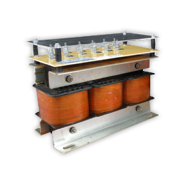
Three-Phase Motor Starting Autotransformer Unit
Three-Phase Motor Starting Autotransformer with Multi-Taps
Motor Rating Range 5 HP to 1000 HP
Standard Start Duty 6 Starts / Hour (Other on Request)
Start Cycle Duration 15 Seconds Continuous Acceleration
Standard Intermediate Taps 60%, 70%, 80%, 100%

Motor Starting Autotransformer Dimensions (10 HP to 150 HP)

Dimensions in mm
Motor Rating (HP) Length (mm) Width (mm) Height (mm) Mounting X (mm) Mounting Y (mm)
1020515024016575
1520516024016592
20205165240165102
2531017024525592
3031517024525592
35310175240255105
40310185240255105
45310200245255120
55310220255255135
60310230285255130
90365240385300140
100365240385300160
150365240385300165
System Integration

Worldwide Applications & Ordering Specification Guide

Key applications across global industrial infrastructure and the parameters needed for rapid engineering review.

Voltage System Matching for Export Machinery

Interconnecting machinery across different national supply grids without the bulk and heat penalty of isolation transformers:

  • Stepping between 480V (North America), 415V (UK/India/Australia), 400V/380V (EU/Asia), and 208V/220V systems.
  • Industrial servo drives, automation machinery, and CNC machining centers.
  • Static voltage stabilizers, dimmer controllers, and uninterruptible power supply lines.

Data Required for Technical Review & Quotation

To receive a precise engineering proposal and guaranteed performance schedule, provide:

  • Design capacity (kVA or HP) and rated system frequency (50 Hz or 60 Hz).
  • Highest and lowest operational system voltages (input and target output).
  • Tapping percentage requirements (e.g. ±2.5%, ±5%, or motor starting 60-70-80%).
  • Duty cycle (continuous or number of starts per hour for motor starting).
  • Preferred IP protection index (open IP00, IP23 louvred, or IP42/IP54 indoor/outdoor).

Speak With an Application Engineer

Whether you need a custom-wound 5000 kVA step-down autotransformer or a heavy-duty reduced-voltage motor starting unit for challenging plant environments, our engineering team provides rapid turnaround design calculations and worldwide shipping quotations.

Inquire Now