Isolation Transformer
3 Phase Electrical Power Isolation Transformer (0.5kVA – 5000kVA)
In high-demand industrial electrical distributions, unexpected transients, voltage surges, and common-mode harmonic noise can degrade sensitive electronics, disrupt automation networks, or cause catastrophic insulation failure. Prima Transformers engineers and manufactures high-efficiency Three Phase Electrical Power Isolation Transformers that establish complete electrical and physical separation between the input power grid and downstream branch circuits.
Built upon a rigid, precision-stacked three-legged core structure using premium cold-rolled grain-oriented (CRGO) lamination steel, our transformers feature dedicated primary and secondary windings on each limb. By floating output windings safely from supply ground references (bonding configured per installation requirements), these units eliminate ground loops, suppress electrical spikes, and deliver pure, uninterrupted power to downstream machinery.
Engineered for Stringent Export Standards
Fully certified to IEC 61558-2-4, IEC 60076, and IS 2026/11171 standards with genuine CE compliance, vacuum pressure impregnation (VPI), and stringent computerised routine tests before dispatch.
General Purpose Isolation Transformers
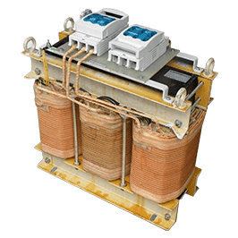
General Purpose Isolation transformers step down primary distribution lines (up to 750V) to localized service voltages inside commercial complexes, heavy data centres, and industrial processing floors. These dual-winding inductive isolators eliminate hazardous ground-fault feedback while significantly minimizing required runs of bulky, low-voltage power cables, thereby mitigating line losses and infrastructure costs.
Recommended Application Loads:
- Industrial facility general lighting and low-noise auxiliary panels
- Standard induction motors and compressors (direct online or soft-started)
- Precision resistive furnace and process heating configurations
- Laboratory automation instruments and cleanroom equipment
Drive Isolation Transformers (DIT)
Modern Variable Frequency Drives (VFDs) and Silicon Controlled Rectifier (SCR) controls inject massive non-linear harmonic distortion, thermal stress, and mechanical switching forces into electrical infrastructure. Prima's custom-engineered Drive Isolation Transformers (DIT) are explicitly tailored to mitigate these challenges without core saturation.
- High Harmonic Tolerance: Robust core dimensioning handles elevated flux density without overheating.
- Mechanical Coil Bracing: Reinforced winding structures resist severe mechanical forces caused by cyclical high inrush currents.
- Stray Loss Minimization: Optimized conductor transposition keeps eddy current losses exceptionally low.
- Enhanced Thermal Dissipation: Generous axial cooling ducts ensure prolonged thermal life under elevated THD.
Advanced Mechanical & Electrical Construction
Every isolation transformer manufactured at our 5,500 m² Santej facility incorporates high-reliability components engineered for 24/7 continuous industrial endurance.
- Acoustic Isolation Pads: Core and coil assemblies mounted on anti-vibration damping pads to minimize operational hum and noise.
- Bolted Heavy-Duty Terminations: Precision-machined, copper/tin-plated busbars and terminals suited for copper or aluminium lugging.
- Robust Protective Enclosures: Standard IP00 open frames up to IP23/IP42 ventilated sheet steel (powder coated) with lifting lugs and bi-directional wheels.
- Stainless Steel Enclosure Options: Custom 304 or 316 grade stainless steel housings available for corrosive, marine, or chemical processing plants.
- Seismic Qualified Bracing: Certified structural framing engineered to withstand earthquake seismic shock spectrum requirements.
- High-Conductivity Conductors: Electrolytic-grade continuous Copper (Cu) or premium Aluminium (Al) wire/strip windings.
- Dedicated Grounding Infrastructure: Continuous copper, aluminium, or galvanized iron grounding bus bar integrated into the core chassis.
- Vacuum Pressure Impregnation (VPI): Deep polyester/epoxy solvent-free resin impregnation curing protects coils against moisture and atmospheric contaminants.
- Primary Voltage Matching Taps: Standard ±2.5%, ±5% de-energized off-circuit taps provided to match unstable incoming network voltages.
- 100% Comprehensive Routine Inspection: Automated testing for winding resistance, turns ratio, polarity, load/no-load loss, DVDF, and insulation integrity.
Technical Specifications
Engineered to deliver high operating efficiency and comprehensive galvanic isolation across versatile power ratings.
Dimensional Data & Mechanical Footprint
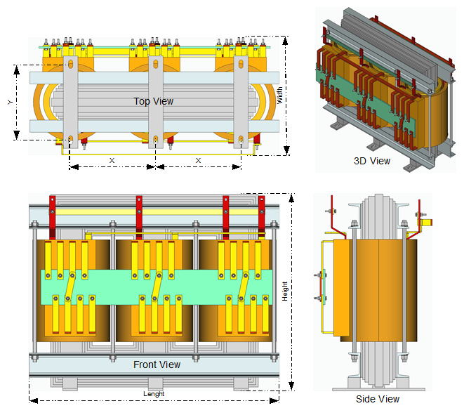
Reference dimensions for standard industrial ratings. Tailored enclosure footprints and terminal configurations are available upon request.
| Rating (kVA) | Length (mm) | Width (mm) | Height (mm) | Mounting X (mm) | Mounting Y (mm) | Slot Size (mm) | Weight (kg) | Frame Type |
|---|---|---|---|---|---|---|---|---|
| 0.5 | 180 | 125 | 200 | 160 | 90 | 8 x 20 | 11 | Type A |
| 0.75 | 240 | 121 | 240 | 160 | 75 | 8 x 20 | 13 | Type A |
| 1.0 | 240 | 120 | 240 | 160 | 75 | 8 x 20 | 14 | Type A |
| 1.25 | 240 | 135 | 240 | 160 | 90 | 8 x 20 | 19 | Type A |
| 1.5 | 240 | 145 | 240 | 160 | 100 | 8 x 20 | 21 | Type A |
| 2.0 | 300 | 150 | 300 | 180 | 90 | 10 x 25 | 26 | Type A |
| 2.5 | 300 | 160 | 300 | 180 | 100 | 10 x 25 | 30 | Type A |
| 3.0 | 300 | 170 | 300 | 180 | 110 | 10 x 25 | 34 | Type A |
| 4.0 | 300 | 180 | 300 | 180 | 120 | 10 x 25 | 41 | Type A |
| 5.0 | 360 | 200 | 360 | 200 | 135 | 13 x 28 | 53 | Type A |
| 6.0 | 360 | 210 | 360 | 200 | 145 | 13 x 28 | 61 | Type A |
| 7.5 | 360 | 210 | 360 | 200 | 145 | 13 x 28 | 65 | Type A |
| 10.0 | 360 | 215 | 360 | 200 | 150 | 13 x 28 | 72 | Type A |
| 12.5 | 360 | 215 | 360 | 200 | 150 | 13 x 28 | 83 | Type A |
| 16.0 | 420 | 250 | 420 | 220 | 170 | 13 x 28 | 110 | Type A |
| 20.0 | 420 | 260 | 420 | 220 | 180 | 13 x 28 | 127 | Type A |
| 25.0 | 480 | 285 | 460 | 220 | 200 | 13 x 28 | 161 | Type A |
| 30.0 | 520 | 315 | 520 | 220 | 200 | 13 x 28 | 201 | Type A |
| 35.0 | 520 | 315 | 520 | 220 | 205 | 13 x 28 | 222 | Type A |
| 40.0 | 550 | 320 | 550 | 220 | 210 | 13 x 28 | 232 | Type A |
| 45.0 | 550 | 350 | 550 | 220 | 210 | 13 x 28 | 261 | Type A |
| 50.0 | 550 | 400 | 550 | 220 | 265 | 13 x 28 | 260 | Type A |
| 60.0 | 600 | 400 | 600 | 400 | 270 | 17 x 35 | 285 | Type B |
| 75.0 | 600 | 500 | 600 | 400 | 265 | 17 x 35 | 329 | Type B |
| 100.0 | 600 | 500 | 600 | 400 | 270 | 17 x 35 | 400 | Type B |
| 125.0 | 750 | 450 | 700 | 400 | 240 | 17 x 35 | 500 | Type B |
| 150.0 | 750 | 450 | 700 | 400 | 240 | 17 x 35 | 550 | Type B |
| 200.0 | 1050 | 500 | 950 | 300 - 300 | 400 | 17 x 35 | 750 | Type C |
| 250.0 | 1200 | 500 | 950 | 350 - 350 | 400 | 17 x 35 | 825 | Type C |
| 300.0 | 1200 | 500 | 950 | 350 - 350 | 400 | 17 x 35 | 900 | Type C |
| 400.0 | 1250 | 600 | 1050 | 400 - 400 | 400 | 17 x 35 | 1200 | Type C |
| 500.0 | 1400 | 600 | 1050 | 400 - 400 | 500 | 17 x 35 | 1450 | Type C |
| 750.0 | 1500 | 700 | 1200 | 450 - 450 | 500 | 17 x 35 | 1650 | Type C |
| 1000.0 | 1620 | 990 | 1500 | 450 - 450 | 500 | 17 x 35 | 2100 | Type C |
| 1250.0 | 1800 | 990 | 1500 | 450 - 450 | 500 | 17 x 35 | 2800 | Type C |
Engineering Note: Units larger than 1000kVA to 5000kVA are engineered on a project-specific basis. Physical dimensions and total weights represent standard manufacturing baselines and may be adjusted based on enclosure IP rating, temperature rise class, and terminal cubicle requirements.
Mounting Diagram - Type A
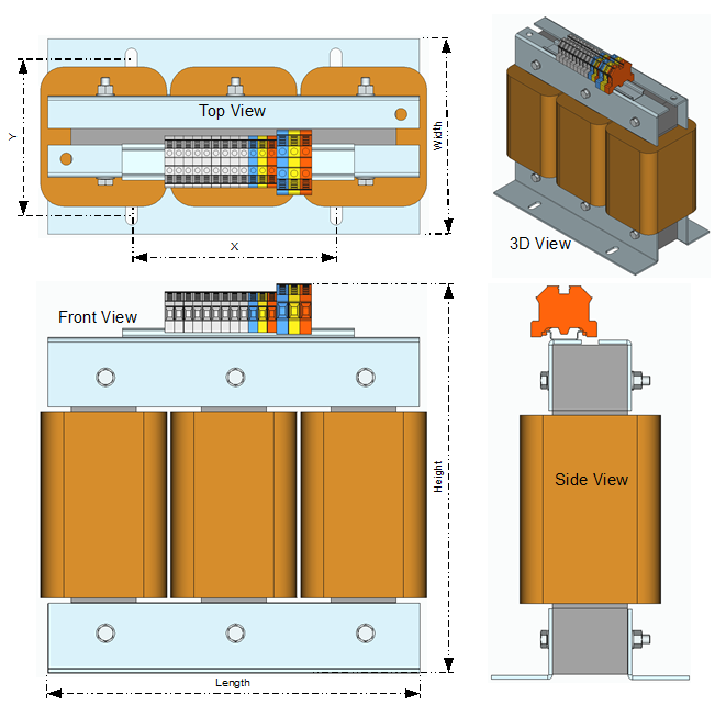
Mounting Diagram - Type B
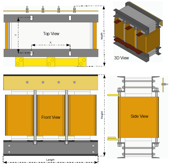
Mounting Diagram - Type C