 CEMarked CEMarked
Select from precision-wound output line reactors, harmonic filtering chokes, and custom inductive apparatus calibrated to support IEEE 519 compliance and extended motor insulation lifespan.
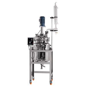
Thermal-jacketed continuous stirred reactor built for biopharma pilot labs in Cambridge & Boston.
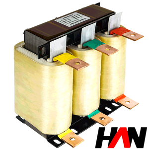
High-saturation magnetic core engineered to reduce total harmonic distortion and line notching.
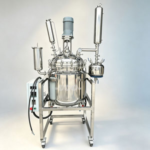
Precision-controlled stirred laboratory reflux reactor equipped for high chemical integrity.
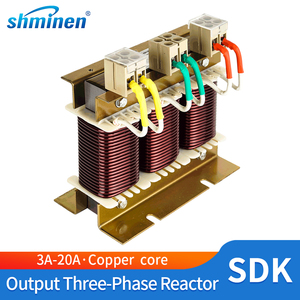
Dedicated dv/dt limiter suited for distributed fractional-to-mid horsepower automated lines.
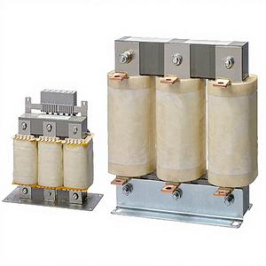
Engineered for seamless direct-fit integration with mainstream European & US drive chassis.
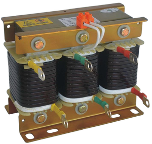
Detuned reactor preventing harmonic resonance in automated capacitor banks and MCC cabinets.
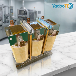
Scalable inductive chokes rating from 0.75kW to 600kW for heavy-load facility infrastructure.
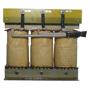
Vacuum pressure impregnated (VPI) Class H assembly designed for long continuous motor feeds.
Variable Frequency Drives (VFDs) utilizing insulated-gate bipolar transistors (IGBTs) switch at carrier frequencies between 2 kHz and 16 kHz. While this high-speed pulse-width modulation (PWM) improves rotational positioning and electrical efficiency, it induces exceptionally steep voltage rise times (dv/dt rates exceeding 10,000 V/µs). When pulse propagation travels along transmission cables connecting industrial panels to induction motors, impedance mismatches cause reflective wave phenomena. For facilities in Greater Boston operating with long motor lead runs (surpassing 50 to 100 feet), voltage reflection can amplify peak terminal voltages up to 2.5 times the nominal DC bus potential, puncturing NEMA MG1 Part 31 motor winding insulation and triggering early-stage bearing fluting.
An output line reactor (or load reactor) inserted in series between the PWM inverter output and the driven load adds calibrated inductive reactance ($X_L = 2\pi f L$). This performs three mission-critical operational corrections: it rounds off steep dv/dt wavefronts to safe operational ceilings (<1,000 V/µs), suppresses high-frequency common-mode leakage currents through motor bearings, and reduces audible magnetic resonance within the stator core. Incorporating precision 3% or 5% impedance output line reactors ensures long-term operational resilience across manufacturing infrastructure.
Boston represents a unique industrial landscape where cutting-edge biotechnology converges with legacy infrastructure and demanding coastal operational profiles.
From Kendall Square in Cambridge to the Seaport Innovation District, high-density biopharma labs mandate 100% continuous outside air exchanges. Variable-speed air handling units (AHUs), chillers, and exhaust fan motors are located hundreds of feet away on facility rooftops or sub-basements. Our load reactors cushion line reflections across extended cable trays, preventing micro-surges that can trigger sensitive optical cleanroom analyzers.
Along the Route 128 Technology Corridor and MetroWest industrial parks, fulfillment mega-hubs operate high-density multi-axis pick-and-place drives and variable-speed sorting belts. Rapid duty cycles and frequent accelerations produce rapid inductive kickbacks. Our 3-phase series line reactors isolate cross-talk between co-located servo drives and programmable logic controllers (PLCs).
Operating in Boston Harbor and regional commercial shipyards demands resilient marine-grade protection. Moisture, salt spray, and shore-to-ship variable power inverters can destabilize induction pumps and thruster winches. Our Class H, vacuum-pressure-impregnated (VPI) reactors resist corrosion and limit harmonic degradation within closed electrical distribution networks.
Select the optimized inductive drop to balance motor terminal voltage and thermal characteristics.
| Operational Metric | 3% Impedance Line/Load Reactor | 5% Impedance Line/Load Reactor | Application Recommended Threshold |
|---|---|---|---|
| Max Lead Distance | Up to 100 - 150 Feet | Up to 300 - 500 Feet | Use 5% for long vertical conduit runs in high-rise lab facilities |
| dv/dt Damping Ratio | 60% - 75% Reduction | Up to 85% - 92% Reduction | Crucial for older non-inverter-duty motors (NEMA Class A/B) |
| THD(i) Attenuation | Reduces current THD to ~35-40% | Reduces current THD to ~28-32% | Select 5% for strict IEEE 519 compliance points |
| Full Load Voltage Drop | Approx. 3% of Nominal Voltage | Approx. 5% of Nominal Voltage | Check supply headroom if nominal line operates at -10% |
| Thermal Rating | Class F (155°C) / Class H (180°C) | Class H (180°C / 200°C VPI) | Equipped for high ambient enclosure conditions (up to 50°C) |
Massachusetts continues to accelerate its Clean Energy and Climate Plan, setting stringent decarbonization mandates that compel legacy industrial facilities, municipal utility systems, and university campus microgrids (such as Harvard, MIT, and Boston University) to transition from fossil-driven systems to high-efficiency electrified heat pump chillers and variable-flow pump skids. As inverter deployment scales rapidly, local utilities—notably Eversource and National Grid—have enforced aggressive point-of-common-coupling (PCC) distortion limits governed by the IEEE 519 standard.
Simultaneously, the widespread installation of large-scale battery energy storage systems (BESS) and commercial solar arrays across Middlesex and Essex counties has increased baseline grid sensitivity to harmonic injection. Unmitigated VFD outputs generate low-order and high-order sideband currents that corrupt sensitive optical metrology, automated liquid handling robotics, and cleanroom bio-reactors. Implementing high-saturation-margin output line reactors with automated thermal cutoffs is no longer merely good practice—it has become a core compliance requirement for facility sign-offs by municipal electrical inspectors under Massachusetts Electrical Code (527 CMR 12.00 / NFPA 70).
Incorporated in 2006 as a 100% subsidiary of Prima Automation (India) Pvt. Ltd., our manufacturing infrastructure spans over 5,500 m² of advanced production lines in Santej, Ahmedabad. Because our group has designed and manufactured PC, PLC, and SCADA-based control panels—including pressurized and explosion-proof panels for hazardous installations—since 1990, we build our line and load reactors with an authentic panel-builder perspective.
Frequent technical considerations addressed by our electrical application engineering desk.
While both rely on precision 3-phase electromagnetic cores, their installation point and design criteria differ significantly. An input line reactor connects between the AC utility feed (e.g., Eversource 480V service) and the VFD's diode/thyristor rectifier. Its primary mission is absorbing mains transients, suppressing input harmonic current distortion (THDi), and protecting the drive's DC bus capacitors. Conversely, an output line reactor (load reactor) is installed between the VFD inverter terminals and the motor. It is subjected to rapid-switching PWM carrier frequencies (up to 16 kHz), requiring low-loss laminations to blunt steep dv/dt spikes, prevent transmission line reflection waves on long cables, and diminish bearing-destroying EDM currents.
Whenever the lead distance between an inverter drive and an induction motor exceeds 50 feet (approx. 15 meters), peak reflective voltages begin to exceed the NEMA MG1 Part 31 threshold (1600V peak rise for inverter-duty motors). For older legacy motors common in Boston's historic manufacturing facilities (NEMA Part 30, rated for only 1000V peaks), an output reactor is recommended for runs over 25 feet. When runs surpass 300 to 500 feet, such as vertical chases in high-rise hospital utilities or expansive pharmaceutical storage facilities, combining a 5% reactor or moving to a dedicated sine-wave filter is mandatory to protect against phase-to-phase short-circuit failure.
To configure the exact core geometry and winding cross-section, provide our application engineers with: (1) System nominal voltage and operating frequency (e.g., 480V AC, 60 Hz), (2) Motor full load amperes (FLA) and horsepower rating, (3) VFD PWM switching (carrier) frequency range, (4) One-way cable distance and conductor type (shielded VFD cable vs. THHN in steel conduit), (5) Desired percent impedance (typically 3% or 5%), and (6) Enclosure requirements (Open-frame IP00 for MCC chassis or NEMA 1 / NEMA 3R outdoor enclosures).
Yes. Our magnetic assemblies undergo automated multi-stage Vacuum Pressure Impregnation (VPI) utilizing Class H high-grade solventless epoxy resin. This process completely fills inter-winding voids, eliminating moisture penetration, neutralizing chemical fumes found in Cambridge synthesis labs, and providing corrosion protection against marine salt air in coastal Boston maritime terminals while reducing operational acoustic noise.
Every shipment carries full compliance documentation, including CE declarations, UL insulation system certifications, and comprehensive factory acceptance test (FAT) reports covering insulation resistance (Megger), high-potential breakdown (Hi-Pot), winding balance, and digital LCR inductance validation calibrated to US industrial specifications.
Our global application engineering team collaborates directly with plant electrical managers, panel fabricators, and consulting engineers to deliver precision-matched line & load reactors, harmonic chokes, and control transformers.
Contact Us