CEMarked CEMarked
From single-phase low-voltage control circuits to multi-MVA substation oil transformers, each unit is manufactured under tight quality tolerances to withstand voltage fluctuations and rigorous duty cycles across European industrial plants.
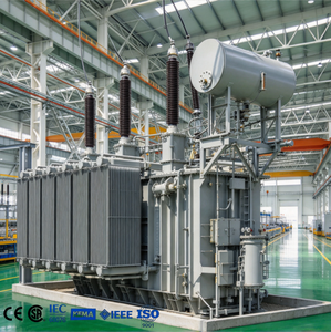
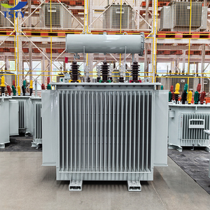
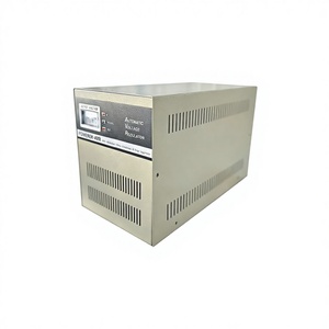
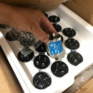
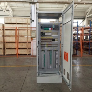
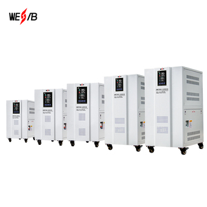
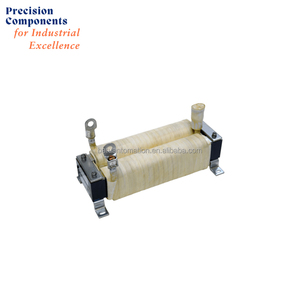
As Poland cements its position as Central and Eastern Europe’s undisputed epicenter for automated machinery manufacturing, automotive tier-1 manufacturing (Katowice, Wrocław, Poznań), and logistics hub automation, the requirements for control transformers (CTs) have shifted dramatically beyond standard electrical isolation.
In contemporary automation cabinets built across Lower Silesia (Dolnośląskie) and Upper Silesia (Śląskie), industrial control transformers serve as the bedrock of control circuit reliability. Under Polish and harmonized European Union standardization, an industrial control transformer is governed primarily by PN-EN 61558-1 (General safety of transformers, power supplies, and reactors) and PN-EN 61558-2-2 (Particular requirements for control transformers). Unlike conventional distribution transformers or basic isolation units, an industrial control transformer must exhibit an exceptionally low secondary internal impedance drop during momentary high inrush inductive conditions—typically encountered when energizing contactors, large solenoids, motor brakes, and safety relay coils.
Modern European directives, including the Low Voltage Directive (LVD) 2014/35/EU, the Electromagnetic Compatibility (EMC) Directive 2014/30/EU, and the strict efficiency thresholds mandated by EU Ecodesign Regulation 2019/1783, demand optimal core geometries and superior grain-oriented silicon steel (CRGO). OEMs exporting machinery from Poland to global markets face severe penalties if power quality anomalies or premature dielectric breakdowns occur due to poorly engineered magnetic components.
| Engineering Parameter | Standard Commercial Grade | Custom OEM Polish Industrial Standard | Direct Technical Impact |
|---|---|---|---|
| Magnetic Core Material | Standard Non-Oriented Silicon Sheet | Laser-Treated M3/M4 High-Grade CRGO Core | Drastically reduces core eddy losses ($P_0$), no-load excitation currents, and acoustic humming (<42 dBA). |
| Inrush VA Surge Capability | 3x to 4x Rated Continuous VA | Up to 8x - 10x Rated VA at cos φ = 0.3 | Prevents secondary voltage sagging below 85% of nominal, avoiding contactor drop-outs or PLC resets. |
| Insulation System Class | Class B (130°C) or Class F (155°C) | Class H (180°C) with Vacuum Pressure Impregnation (VPI) | Surpasses harsh ambient factory conditions, offering long thermal life under continuous 24/7 duty cycles. |
| Dielectric Test Voltage (DVDF) | 2.0 kV / 1 Minute standard test | Double Voltage Double Frequency (4.2 kV / 120s) | Guarantees inter-turn and inter-winding dielectric breakdown immunity against heavy switching transients. |
| Primary Tapping Flexibility | Fixed Dual Voltage (230V / 400V) | Multi-Tap: 208V, 230V, 380V, 400V, 415V, 460V, 500V, 690V | Empowers Polish machine builders to ship a unified panel layout globally without redesigning internal power architecture. |
Our custom control and power magnetics are tailored specifically to the operational environments, regional manufacturing specializations, and grid conditions found throughout Poland.
Concentrated along the Katowice Special Economic Zone (KSSE) and Wrocław tech corridors, automated welding cells, stamping presses, and lithium-ion pouch cell assembly lines generate severe electrical noise and rapid inductive surges. Custom control transformers equipped with electrostatic shielding (Faraday screens) between primary and secondary windings prevent high-frequency transients from infiltrating sensitive servo encoders, PLC I/O modules, and robotics controllers.
In the heavy industrial belt of Śląskie, steel fabrication and precision CNC machining plants experience frequent grid voltage sags caused by the direct-on-line starting of large induction motors. Pairing three-phase servo automatic voltage stabilizers with high-isolation step-down control transformers guarantees an ultra-tight ±1% voltage stabilization window, preserving spindle accuracy, tool longevity, and finishing quality.
With Central Poland (Łódź, Piotrków Trybunalski) serving as the key logistics artery for mainland Europe, multi-kilometer automated parcel sortation systems, automated guided vehicles (AGVs), and high-bay stacker cranes demand thousands of continuous operating hours. Our vacuum-varnished, dry-type control transformers operate silently and reliably inside compact, IP54/IP65 electrical cabinets without excessive heat buildup.
Facilities such as PKN Orlen in Płock, copper mines in Lubin (KGHM), and chemical processing complexes in Kędzierzyn-Koźle operate under explosive gas and combustible dust atmospheres. We engineer customized control transformers encapsulated in flameproof enclosures, meeting ATEX Directive 2014/34/EU and EN 60079 requirements for Zone 1 and Zone 2 safety integrity.
As Poland accelerates its renewable transition along the Baltic shoreline (Gdańsk, Szczecin) and across Greater Poland, auxiliary substation control circuits require ruggedized step-down transformers capable of resisting saline atmospheric corrosion (C4/C5 marine protection), severe temperature cycling (-25°C to +55°C), and non-linear inverter-fed harmonics.
In Wielkopolska and Mazovia's dairy, agri-food, and pharmaceutical processing lines, rigorous daily washdown procedures using caustic agents are standard. Our transformers feature hermetically sealed epoxy encapsulated cores and anti-tracking terminal assemblies conforming to IP66/IP67 ingress barriers, avoiding moisture ingress and phase-to-ground leakage currents.
How manufacturing nearshoring, energy transition mandates, and harmonic compliance are redefining the transformer supply chain for Polish switchgear integrators.
Global machinery manufacturers are transferring assembly clusters to Poland to lower production lead times while retaining EU-quality compliance. Polish panel shops need flexible, fast-turnaround OEM transformer suppliers who can customize primary voltages (200V to 690V) on short design cycles.
Poland’s Energy Policy until 2040 (Polityka Energetyczna Polski) enforces strict carbon footprint limitations. OEMs are actively ditching legacy lossy transformers in favor of high-permeability CRGO cores that minimize idle no-load watt losses across massive assembly lines.
As Variable Frequency Drives (VFDs) dominate conveyor and pump systems, reflected wave spikes (dv/dt) and 5th/7th/11th order harmonic distortions degrade classic control insulation. Polish system builders now mandate matched line/load reactors and DC link chokes inside their primary power bills of materials.
Rising industrial real estate costs in Warsaw, Kraków, and Poznań have driven electrical panel designs into ultra-dense enclosures. Compact footprints, high volumetric power density, and touch-proof screw-clamp terminals (IP20) are decisive purchasing criteria.
A frequent mistake in Polish panel design is selecting a control transformer solely based on continuous volt-ampere (VA) load. Under inductive switching, contactor pull-in coils exhibit an inrush power factor of cos φ = 0.2 to 0.4, drawing between 500% to 1000% of nominal holding current for 15–50 milliseconds. Our custom magnetic winding geometries maintain secondary voltage at >90% of nominal during peak inrush events, preventing microprocessor reboots and contactor chattering.
We do not just build transformers; we design magnetics from the distinct perspective of an industrial automation system builder. Established in 2006 as a dedicated manufacturing arm of an automation leader operating since 1990, our plant bridges heavy magnetics engineering with digital control technology.
Equipped with multi-axis automated CNC foil and wire winding machinery, vacuum pressure impregnation (VPI) autoclaves, and temperature-controlled curing ovens. We reliably manufacture units from delicate 50VA control transformers up to 5000kVA power units and 2500A inductors.
Zero defects leave our testing bays. Every single unit undergoes automated routine testing including: Double Voltage Double Frequency (DVDF) induced overvoltage test, open-circuit/short-circuit computerized load loss recording, Megger insulation resistance verification, digital LCR inductance analysis, and infrared thermal imaging.
We provide full mechanical customization for European machine exporters: specific terminal blocks (Phoenix Contact / WAGO / Weidmüller compatibility), custom powder-coated IP23/IP54/IP65 enclosures, private label rating plates with your part numbers and barcodes, and full CE/RoHS certification dossiers.
Real-world technical and commercial answers addressing standard compliance, shipping logistics to Poland, lead times, and customization parameters.
Our custom control transformers strictly adhere to PN-EN 61558-1 (Safety of power transformers, power supply units and similar devices) and PN-EN 61558-2-2 (Particular requirements for control transformers). Each manufactured unit carries verified CE marking fulfilling the EU Low Voltage Directive (LVD) 2014/35/EU and the EMC Directive 2014/30/EU. Where requested by export clients supplying North American markets, UL/CSA insulation class recognized materials are integrated.
Control circuits experience instantaneous power factor drops (cos φ = 0.2 to 0.4) during contactor and solenoid coil energization. We calculate the total Inrush Volt-Amperes (inrush VA) alongside the continuous sealed VA. By employing oversized secondary copper conductor cross-sections, low-loss grain-oriented silicon steel (CRGO), and optimized winding geometry, our designs keep the momentary secondary voltage drop well within the allowable 5%–10% margin, avoiding contactor coil dropouts or control relay chatter.
We routinely configure multi-tap primary windings accommodating standard Polish/EU grid voltages (230V / 400V 50Hz) as well as global nominal supply voltages: 208V, 220V, 240V, 380V, 415V, 440V, 480V, 575V, and 690V (both 50Hz and 60Hz). Secondary taps can be configured for standard control levels (24V AC, 48V AC, 115V AC, or 230V AC) with optional center taps or dedicated electrostatic Faraday shielding.
Yes. Drawing on our parent organization’s extensive engineering background since 1990 in manufacturing pressurized, flameproof, and intrinsically safe panels, we build hazardous area transformer systems conforming to the ATEX Directive 2014/34/EU and PN-EN 60079 standards for deployment in petrochemical plants (such as Płock), mining complexes (Upper Silesia), and chemical processing zones.
Every single unit undergoes comprehensive automated computerized routine testing in our Ahmedabad facility prior to export. This includes: Double Voltage Double Frequency (DVDF) induced overvoltage withstand, computerized Open-Circuit (no-load loss $P_0$ and current $I_0$) and Short-Circuit (load loss $P_k$ and impedance voltage $U_k$) tests, high-voltage dielectric insulation tests (up to 4.2kV), milli-ohm DC winding resistance measurement, digital LCR inductance testing, and infrared thermographic inspections. Full certified inspection test reports (ITR) and FAT certificates are provided with every delivery batch.
For custom-engineered prototype samples, lead times range between 10 to 14 working days. Volume OEM production batches typically require 3 to 4 weeks. Shipments to Poland are channeled via direct ocean freight to major sea gateways including the Port of Gdańsk or Gdynia, or alternatively through Hamburg/Rotterdam with bonded truck transit directly to your manufacturing warehouse in Katowice, Wrocław, Warsaw, or Poznań. Air express options are available for urgent project schedules.
Line reactors (installed on drive input) introduce controlled percentage impedance (typically 3% or 5%) to attenuate current harmonics, suppress high-voltage AC line spikes, and shield the front-end rectifier. Output load reactors limit the rapid voltage rise rate (dv/dt) caused by high-frequency IGBT switching, protecting motor insulation systems against premature dielectric puncture and mitigating shaft voltage bearing damage on motor cable runs exceeding 30 meters.
To prepare an exact engineering quotation, our design engineers require: rated power capacity (VA or kVA), primary voltage(s) and tapping intervals, secondary voltage(s) and full-load currents, frequency (50Hz / 60Hz), number of phases, insulation thermal class (e.g., Class F or H), required enclosure IP rating (e.g., Open IP00, IP20, IP23, IP54), duty cycle profile, and any specific inrush VA or dielectric withstand requirements.