 CEMarked CEMarked
A granular guide for electrical EPC contractors, municipal distribution utilities, substation designers, and cross-border industrial procurement executives.
As industrial automation scales and modern power grids undergo seismic transitions toward decentralized architectures, selecting a verified, field-tested pad-mounted transformer exporter is a mission-critical infrastructure decision. A pad-mounted (or pedestal-mounted) transformer represents a fully integrated, tamper-resistant, outdoor-rated distribution node designed to interface medium-voltage underground reticulation lines (typically 2.4 kV up to 35 kV and 34.5 kV systems) directly with low-voltage commercial, industrial, or residential facilities (120/240 V, 208Y/120 V, 480Y/277 V, or 600 V). Unlike conventional oil-immersed substation transformers installed within walled perimeters, pad-mounted transformers operate in public-access locations, mandating strict compliance with IEEE C57.12.28 tamper-resistance standards, low audible decibel emissions, zero oil-leaching hermetic seals, and dependable circuit protection mechanisms.
Backed by our corporate lineage founded under Prima Automation in 1990 and formalized via Prima Transformers Pvt. Ltd. in 2006, our facility in Santej, Ahmedabad (India) brings more than 25 years of specialized electromagnetic domain expertise to global transformer export operations. Operating an expansive 5,500 m² modern manufacturing campus, we engineer single-phase and three-phase pad-mounted units, control and power transformers ranging from 50 VA up to 5,000 kVA, line/load reactors up to 2,500 A, and high-harmonic filters up to 500 HP. By unifying automated core-slitting, step-lap lamination stacking, computer-controlled foil/wire winding, advanced vacuum pressure impregnation (VPI), vacuum drying, and rigorous double voltage double frequency (DVDF) induced overvoltage testing under one roof, we eliminate intermediate supply chain delays and deliver robust magnetic solutions that meet IEEE, ANSI, CSA, and IEC standards for demanding international clients.
"In underground distribution networks, total operational reliability is non-negotiable. Over 70% of lifecycle transformer failures worldwide stem from localized hot spots in windings, dielectric degradation under continuous harmonic loading, or environmental corrosion breaches at cabinet seams. Our export-grade units mitigate these exact failure modes through advanced thermal profiling, high-grade C5-M anti-corrosion barrier coatings, and laser-welded hermetic tanks."
Rigorous factory testing, international certifications, and custom winding topologies engineered for export markets.
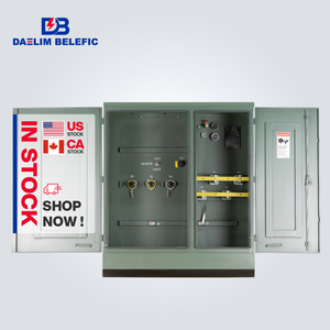
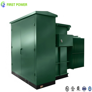
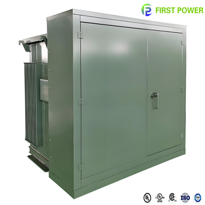
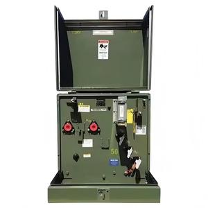
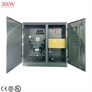
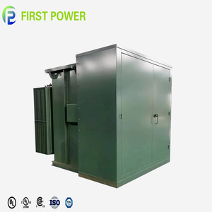
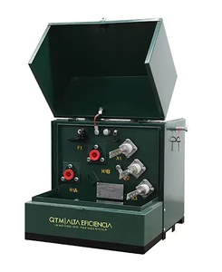
Comprehensive baseline electrical, physical, and dielectric parameters across our standard export-line pad-mounted units.
| Parameter | Three-Phase Commercial (ZGS / ANSI) | Single-Phase Residential (American Type) | Industrial Renewable Collector Pad-Mount |
|---|---|---|---|
| Power Rating Spectrum | 75 kVA to 5,000 kVA continuous | 15 kVA to 250 kVA (standard 167 kVA) | 1,000 kVA to 3,750 kVA (custom to 5,000 kVA) |
| Primary Voltage Classes | 4.16 kV, 12.47 kV, 13.2 kV, 13.8 kV, 24.94 kV, 34.5 kV | 7,200/12,470Y V, 14,400/24,940Y V, 19,920/34,500Y V | 13.8 kV, 22 kV, 33 kV, 34.5 kV, 35 kV collector buses |
| Secondary Voltages | 208Y/120 V, 480Y/277 V, 600Y/347 V, 415Y/240 V | 120/240 V split phase, 240/480 V | 400 V, 600 V, 690 V inverter/ESS duty, or 800 V AC |
| Feed Architecture | Loop Feed (6 MV Bushing Wells) or Radial (3 Bushings) | Radial Feed (1 Bushing) or Loop Feed (2 Bushings) | Loop Feed with multi-position four-way LBOR switch |
| Basic Impulse Level (BIL) | 60 kV, 75 kV, 95 kV, 125 kV, 150 kV, 200 kV Crest | 60 kV, 95 kV, 125 kV Crest | 95 kV to 200 kV Crest with lightning arresters |
| Dielectric Coolant Fluid | Mineral Oil (Type II ASTM D3487) / FR3 Ester Fluid | Inhibited Mineral Oil / Natural Bio-Ester Fluid | Envirotemp™ FR3™ / K-Class Fire-Safe Fluid |
| Winding Metallurgy | Electrolytic Copper or EC-Grade Aluminum with Diamond Epoxy Paper | High-purity Magnet Wire / Continuous Copper Strip | Heavy foil wound copper/aluminum with harmonic K-factor rating |
| Overcurrent Protection | Bay-O-Net Expulsion Fuse in series with Current-Limiting Backup | Dual-fuse protection: Bay-O-Net + ELSP fuse | Bay-O-Net, Partial-Range Current Limiting, VFI vacuum interrupters |
| Cabinet Integrity Standard | IEEE C57.12.28 (Tamper-Resistance, Penta-Head locking) | ANSI C57.12.28 / C57.12.29 coastal corrosion resistance | Heavy-gauge 304 or 316L Stainless Steel, C5-M marine rating |
Pad-mounted distribution transformers exported by verified manufacturers feature a strictly compartmentalized layout divided into two distinct zones: a low-voltage (LV) wiring chamber and a high-voltage (HV) termination enclosure, segregated from the sealed fluid tank. The enclosure doors are mechanically interlocked such that access to the high-voltage chamber cannot be attained without first unlatching and opening the low-voltage door, preventing unauthorized access by personnel or the public. The HV section utilizes dead-front loadbreak bushing wells designed for insulated elbow connectors conforming to IEEE 386, empowering technicians to safely disconnect or switch energized circuits using hot-stick tools without exposing bare medium-voltage busbars.
How our Ahmedabad manufacturing plant guarantees zero-defect manufacturing through computerized test benches and automation heritage.
Originating under Prima Automation (India) Pvt. Ltd., an established manufacturer of PC, PLC, SCADA, and hazardous-area flameproof control systems since 1990. We design transformers through an automation systems lens, engineering for true electrical stability.
Situated in Santej, Ahmedabad, our purpose-built 5,500 m² plant houses specialized micro-gap core slitters, automated precision foil winders, continuous annealing ovens, and hermetic tank welding bays, producing over 3,000 units annually for global EPC deployment.
Every single unit undergoes an exhaustive testing regimen before factory release: open/short circuit loss measurement, computerized DVDF induced overvoltage validation, milli-ohm DC winding resistance, insulation resistance (Megger), and digital LCR analysis.
Our core export mission is manufacturing transformers bearing recognized CE marks and complying directly with IEEE C57.12.00, IEEE C57.12.34, DOE 2016 efficiency, and IEC 60076 directives, facilitating seamless interconnection into international electrical grids.
Analyzing structural market dynamics, supply chain constraints, and total cost of ownership (TCO) models driving modern capital allocation.
Global lead times for North American and European domestic distribution transformers have extended to unprecedented windows of 80 to 140 weeks due to structural grain-oriented electrical steel (GOES) and copper rod shortages. Forward-thinking utilities and tier-1 EPC contractors are actively diversifying procurement pathways, signing framework purchase agreements with established Indian and Asian manufacturing exporters who maintain agile stocking strategies and guarantee 16-to-26-week delivery cycles.
Procurement departments have shifted decisively away from evaluating purely upfront capital expenditure (CapEx) toward rigorous Total Cost of Ownership (TCO) mathematical modeling. Using formalized equations such as TCO = Purchase Price + (A × No-Load Loss) + (B × Load Loss), buyers evaluate transformers over a 30-year operational horizon. Our low-loss step-lap silicon steel cores and optimized conductor geometries are tailored to drastically reduce capitalization penalties, maximizing net lifetime payback.
The explosive rollout of artificial intelligence computing clusters and hyperscale data centers requires dedicated modular power substations capable of handling step-up/step-down transformation with heavy continuous harmonic currents (K-factor 13 to 20). Pad-mounted transformers engineered with electrostatically shielded windings, upgraded neutral sizing (200%), and advanced thermal insulation are experiencing rapid double-digit compound procurement growth across global tech corridors.
Emerging engineering breakthroughs in biodegradable dielectric media, amorphous core metallurgy, and intelligent digital sensing.
Traditional naphthenic mineral oil is rapidly being phased out in favor of natural biodegradable ester fluids derived from renewable plant seeds. Natural esters offer a high flash/fire point exceeding 360°C (classified as K-Class fluid under IEC 61039 / NEC Article 450), permitting transformers to be installed in close proximity to commercial building facades without constructing concrete fire barrier walls. Furthermore, esters actively extract moisture from paper insulation, effectively extending mechanical winding lifespan by up to 200%.
By replacing traditional Cold-Rolled Grain-Oriented (CRGO) silicon steel laminations with amorphous ribbon alloy cores (non-crystalline glass metallurgy), core hysteresis and no-load losses (standing core losses) are reduced by 65% to 75%. In utility networks with cyclical or low average loading profiles, amorphous pad-mounted units curtail massive annual megawatt-hour energy waste, aligning directly with Tier 2 EcoDesign (EU 548/2014) and US DOE 2016 efficiency mandates.
The standard mechanical thermometer and liquid level dial are evolving into smart sensor arrays. Modern export-grade pad-mounted units now feature optical fiber winding temperature probes, pressure-vacuum-transducers with 4-20 mA or Modbus RTU telemetry outputs, dissolved gas analysis (DGA) hydrogen micro-sensors, and electronic security tamper switches. These sensors transmit real-time telemetry into utility SCADA architectures, enabling predictive condition-based maintenance and preventing catastrophic flashover outages.
Detailed technical answers to common engineering, compliance, testing, and shipping questions encountered during procurement.
A Radial Feed transformer has three high-voltage bushing wells (H1, H2, H3) and is engineered for installation as an endpoint unit on an underground distribution lateral. Power enters the transformer and terminates there. If service to that transformer is interrupted, only that node is de-energized.
A Loop Feed transformer features six high-voltage bushing wells arranged in two sets (H1A, H2A, H3A and H1B, H2B, H3B), coupled with an internal four-position under-oil Loadbreak Oil Rotary (LBOR) switch. This allows power to flow into the transformer and continue out to downstream transformers in a closed ring loop. If a fault occurs anywhere along the underground cable segment, the utility can isolate the faulted cable using the LBOR switch and back-feed power from the opposite direction, restoring power without causing prolonged outages to connected facilities.
At our plant in Santej, Ahmedabad, 100% of manufactured units undergo comprehensive automated computerized testing conforming strictly to IEEE C57.12.90 and IEC 60076 standards. Routine tests include:
1. Winding Resistance Measurement: Verified via high-precision milli-ohm meters at cold state.
2. Voltage Ratio & Vector Phase Displacement: Confirms turns ratio across all primary taps.
3. No-Load Losses & Exciting Current: Performed at 100% and 105% rated secondary excitation voltage.
4. Impedance & Load Losses: Measured under rated frequency to determine true impedance voltage.
5. Applied Voltage Dielectric Test: High-potential test verifying ground wall insulation.
6. Induced Overvoltage Test (DVDF): Double Voltage Double Frequency test performed at 200 Hz to stress inter-turn and inter-layer winding insulation without saturating the magnetic core.
7. Tank Pressure Leak Test: Helium or dry-nitrogen leak test under 50 kPa positive pressure for a minimum 24-hour hold.
Dead-front pad-mounted transformers contain zero exposed, energized metallic components when the front cabinet doors are opened. The medium-voltage bushings are engineered as 200 A bushing wells or 600 A integral deadbreak bushings adhering to IEEE 386. Fully screened, submersible EPDM rubber elbow connectors enclose the cable ends and interface with the bushing wells. Even if an authorized technician opens the high-voltage chamber while the system is energizing 15 kV or 35 kV, touching the external insulated casing of the elbow connector poses zero shock hazard, provided the semi-conductive outer shield is properly grounded with copper drain wire.
To comply with stringent IEEE C57.12.28 and coastal C57.12.29 enclosure integrity standards, our steel cabinets undergo a thorough seven-stage chemical pretreatment wash, including zinc-phosphate surface conversion. We apply a multi-layer electrostatic thermoset polyester powder coat cured at 200°C, producing a minimum 3.0 mil dry film thickness (DFT). This finish withstands 3,000+ hours of continuous salt-spray testing per ASTM B117 without blistering or creepage. For severe offshore, coastal, or chemical plant applications, we fabricate the entire tank, sill, and cabinet doors using grade 304L or marine-grade 316L stainless steel finished with C5-M certified protective systems.
To accelerate technical review and receive an optimized proposal, provide the following parameters:
• Rated Power: Base kVA or MVA capacity (e.g., 500 kVA, 1500 kVA, 2500 kVA).
• System Voltages: Primary MV (e.g., 13.8 kV Delta or 34.5 kV GrdY) and secondary LV (e.g., 480Y/277 V).
• Operating Frequency: 50 Hz or 60 Hz.
• Connection & Vector Group: Dyn1, Dyn11, YNyn0, etc.
• Feed Topology: Radial Feed or Loop Feed with 2-position or 4-position LBOR switch.
• Cooling Fluid: Standard Mineral Oil or K-Class Biodegradable Ester Fluid (FR3).
• BIL & Impedance (%Z): Target impedance and lightning impulse withstand rating.
• Applicable Standard: IEEE C57.12.34 / DOE 2016, CSA C227.4, or IEC 60076.
Whether you require single-phase residential units, multi-megawatt commercial loop-feed substations, or specialized solar/BESS medium-voltage skid transformers, our engineering team in Ahmedabad is ready to support your technical specifications.
Get a Quote