CEMarked CEMarked
Delivering high-performance, low-loss rectification systems engineered to withstand severe harmonic distortion, thermal stress, and heavy DC load surges.
High-reliability components optimized for variable frequency drives, DC links, and continuous industrial process systems.
A rigorous examination of rectifier transformer design criteria for non-sinusoidal waveforms and DC electro-chemical processes.
Rectifier circuits load transformer windings with severe harmonic currents (5th, 7th, 11th, 13th, and higher order). Standard distribution units experience severe overheating due to winding eddy-current losses proportional to the square of the frequency.
Our units utilize continuous transposed conductor (CTC) winding and optimized electrostatic shields designed to accommodate K-Factor ratings up to K-30 without insulation degradation.
Rectification loads—particularly in electrolysis, galvanic coating, and large DC motor drives—are prone to direct short-circuit phenomena and high inrush conditions.
We deploy high-density, pre-compressed insulation spacers, axially locked clamping assemblies, and high-tensile core framing that withstand electrodynamic short-circuit forces up to 25 times nominal current ratings according to IEC 60076-5 standards.
Suppression of total harmonic distortion (THD) at the point of common coupling (PCC) is mandatory under modern grid codes like IEEE 519. We build sophisticated multi-winding systems achieving 12-pulse, 18-pulse, 24-pulse, and 36-pulse configurations.
By engineering vector configurations utilizing extended delta, zig-zag, or multiple phase-shifted star/delta secondary windings (±7.5°, ±15°, 30°), phase cancellation eliminates unwanted harmonic orders upstream.
Engineered technical parameters supporting international industrial standards.
| Core Parameter | Electrolysis & Chemical Duty | VFD Drive & Mining Rectifiers | Traction Substation Class |
|---|---|---|---|
| Rated Capacity | Up to 5000 kVA / 10 MVA units | 100 kVA to 3150 kVA | 500 kVA to 4000 kVA |
| Pulse System Configurations | 12-Pulse, 24-Pulse Interphase | 6-Pulse, 12-Pulse, 18-Pulse Drive | 12-Pulse, 24-Pulse Extended Delta |
| Winding Material | Electrolytic Copper (OFHC) Foil / CTC | Grade-A Enamelled Copper / Strip | High Conductivity Foil / CTC Copper |
| Insulation Class | Class H (180°C) / Class C (220°C) | Class F (155°C) or Class H (180°C) | Class H (180°C) Nomex Enhanced |
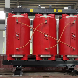
| Cooling Configurations | ONAN / ONAF / OFAF (Liquid Immersed) | AN / AF (Cast Resin Dry Type) | ANAN / ONAF Forced Distribution |
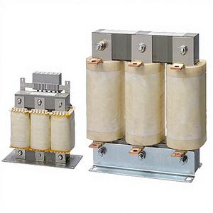
| Harmonic Mitigation | Integrated Interphase Reactors (IPR) | Line/Load Reactors & EMI Filters | Tertiary Delta Compensating Loop |
Operating a dedicated 5,500 m² state-of-the-art facility featuring fully computerized routine and type testing systems.
Equipped with Double Voltage Double Frequency (DVDF) testing rigs to ensure inter-turn and inter-winding dielectric withstand capability across high pulse frequencies.
Computerized Open-Circuit (no-load losses and current) and Short-Circuit (load loss and impedance) measurement benches calibrated for real-time harmonic isolation evaluation.
Precision micro-ohmmeter arrays to verify strict phase balance matching, combined with digital LCR analyzers ensuring tight leakage inductance tolerances essential for parallel rectification paths.
Full-load factory heat run testing evaluated with high-resolution infrared imaging to detect potential localized hot spots induced by circulating stray flux in core clamping plates and tank walls.
Strategic technology developments reshaping the industrial transformer and power conversion landscape.
The global shift toward green hydrogen production via proton exchange membrane (PEM) and alkaline electrolyzers requires mammoth DC power rectifiers. Procurement demands are shifting towards ultra-low-voltage, ultra-high-current transformers (e.g., 100V, 40,000A) requiring complex interphase reactor engineering and specialized water-cooled busbar layouts.
Global decarbonization policies demand ultra-low no-load core losses. The market is increasingly specifying high-grade, domain-refined laser-scribed grain-oriented silicon steel (Hi-B CRGO) and amorphous alloys, yielding a 30% reduction in baseline iron losses under continuous multi-pulse non-sinusoidal harmonic excitation.
Modern EPC contractors and process plants prioritize proactive lifecycle monitoring over reactive maintenance. Specifiers demand smart rectifier transformers equipped with fiber-optic winding temperature probes, online dissolved gas analysis (DGA), and vibration-frequency transmitters linked to SCADA systems.
Comprehensive technical and commercial answers addressing high-intent operational inquiries.
Connect directly with our magnetic applications engineering team for custom simulations, impedance matching calculations, and complete technical specifications.