Santej, Ahmedabad, Gujarat, IndiaCE-Marked Transformers for Export
Serving OEMs & Projects Worldwide
CEMarked
China Top Potential Transformer Manufacturers & Factory
Authoritative OEM/ODM Engineering Guide for Precision Potential Transformers (PT / VT), High-Voltage Instrument Transformers, Medium-Voltage Switchgear Sensors, and Grid-Tie Power Distribution Magnetics
Recommended Power & Potential Transformer Systems
Engineered for mission-critical electrical substations, industrial motor drives, and medium-to-low voltage switchgear assemblies compliant with IEC 61869, IEEE C57.13, and CE testing standards.
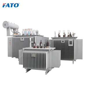
Hermetically sealed mineral oil step-down distribution transformer for 11kV/33kV utility lines, built with low-loss core lamination and high short-circuit withstand.
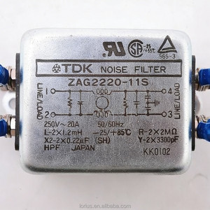
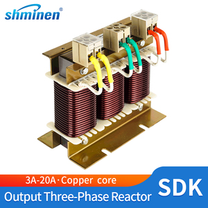
Variable frequency drive load reactor suppressing motor terminal dv/dt spikes, mitigating reflected wave phenomena, and extending motor insulation longevity.
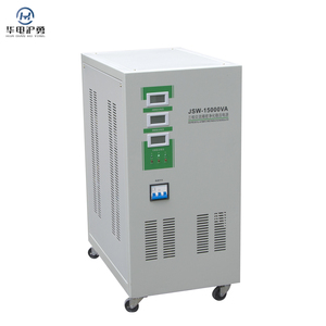
Dedicated industrial climate control system ensuring optimized operating temperatures and relative humidity inside high-density electrical substation control houses.
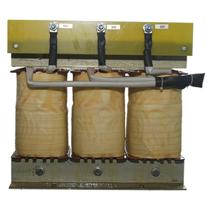
Heavy-duty inductive smoothing reactor engineered with premium grain-oriented silicon steel cores and vacuum pressure impregnated Class H winding insulation.
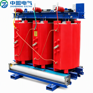
Epoxy cast resin flame-retardant dry-type transformer featuring automated PT100 temperature monitoring, RS485 Modbus telemetry, and ultra-low no-load core losses.
5,500+ m²
Modern Workshop Footprint
50VA - 5MVA
Manufacturing Capacity
0.2 / 0.2S
Revenue Metering Accuracy
100% DVDF
Computerized Routine Testing
Technical White Paper: Precision Potential Transformers in Modern Substation Design
An engineering treatise on metrological precision, insulation coordination, and ferroresonance suppression for electrical utilities, EPC contractors, and switchgear manufacturers.
In alternating current (AC) electrical power transmission, distribution networks, and industrial microgrids, Potential Transformers (PT)—interchangeably termed Voltage Transformers (VT) under international IEC terminology—operate as fundamental metrological transducers. Their critical objective is twofold: step down dangerously elevated primary transmission and distribution voltages (typically ranging from 3.3kV, 11kV, 33kV, up to 132kV and beyond) to standardized, galvanically isolated secondary operating levels (such as 100V, 110V, 115V, or 120V line-to-line), and provide accurate proportional phase and amplitude replication for protective relays, digital fault recorders, revenue billing meters, and SCADA monitoring nodes.
Selecting the appropriate potential transformer manufacturer requires a holistic understanding of electrical stress mechanisms, dielectric breakdown behavior, and magnetic core saturation dynamics. Unlike standard distribution or power transformers whose primary engineering goal is bulk power throughput with high energy efficiency, a potential transformer operates continuously under essentially an open-circuit secondary condition, presenting high excitation impedance. Consequently, the operational fidelity of a PT is judged almost entirely on its Ratio Correction Factor (RCF) and Phase Angle Error (β) under varying burden conditions (volt-amperes, VA) and power factors.
Core Topological Architectures: Inductive PT vs. Capacitive Voltage Transformers (CVT)
Industrial procurement teams frequently weigh the mechanical and economic tradeoffs between Electromagnetic Inductive Potential Transformers (IVTs) and Capacitive Voltage Transformers (CVTs). Inductive voltage transformers utilize conventional high-permeability wound cores (often cold-rolled grain-oriented silicon steel, CRGO, or advanced nanocrystalline alloys) with vacuum-cast epoxy resin or oil-impregnated paper insulation. Inductive units deliver exceptional linear measurement accuracy across both low-voltage switchboards and medium-voltage substations up to 66kV. However, at ultra-high transmission voltages (≥110kV to 500kV), capacitive voltage dividers combined with an intermediate electromagnetic tuning unit become commercially advantageous while simultaneously offering carrier frequency injection capabilities for Power Line Carrier Communications (PLCC).
Within modern indoor metal-clad switchgear assemblies (such as the Siemens 8PT modular designs and KYN28 central switchboards), Cast Resin Dry-Type Potential Transformers have almost completely displaced traditional oil-immersed models. Synthesized with cycloaliphatic epoxy resin compounds cured under controlled vacuum pressure casting cycles, dry-type PTs eliminate dielectric oil leaks, mitigate catastrophic combustible fire hazards, and provide superior partial discharge (PD) resistance under repetitive high dv/dt atmospheric lightning impulses and switching surges.
How global digital transformation, renewable microgrids, and environmental standards are reshaping potential transformer manufacturing and sourcing criteria.
Digital & Optical Voltage Sensors (LPVT)
Transitioning from heavy iron-core designs toward Low-Power Voltage Transformers (LPVT) based on resistive-capacitive dividers and optical Faraday/Pockels-effect sensors. These provide direct point-on-wave digital Merging Unit (MU) outputs compliant with IEC 61850-9-2 Sampled Values (SV).
Active Ferroresonance Suppression
Decoupling inductive PT nonlinear magnetic cores from cable capacitance in ungrounded distribution grids. Modern prospective specifications mandate damping resistors, auxiliary open-delta electronic suppressors, and saturation-resistant cores that withstand transient overvoltages during system ground faults.
SF6 Alternatives & Eco-Solid Insulation
Global decarbonization mandates and stringent F-gas regulations are pushing substation procurement toward Fluoronitrile gas mixtures, synthetic ester dielectric liquids, and recyclable bio-based epoxy resins to maintain low global warming potential (GWP) without sacrificing BIL withstand.
Why Partner With Us: Factory Strengths & Metrology Standards
Rooted in over 25 years of electrical engineering excellence since 1990, backed by a sprawling 5,500 m² state-of-the-art facility delivering custom electromagnetic solutions worldwide.
Computerized Routine Testing
Every single potential transformer undergoes automated open-circuit and short-circuit (OC/SC) ratio verification, winding resistance tests, and computerized phase angle validation to guarantee metrological conformity prior to packaging.
DVDF Overvoltage Testing
Full implementation of Double Voltage Double Frequency (DVDF) induced overvoltage withstand testing, confirming inter-turn and inter-layer winding dielectric strength to safeguard against severe grid transients and lightning surges.
Partial Discharge & Megger Rig
In-house shielded testing bays equipped with ultra-sensitive partial discharge detectors (≤5pC at rated voltage) and high-voltage Megger insulation resistance instruments ensuring long-term void-free epoxy casting integrity.
OEM Switchgear Customization
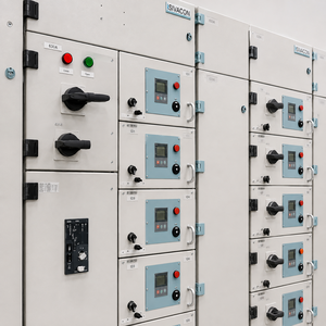
Backed by decades of experience building PLC/SCADA control cabinets and modular switchboards, we engineer custom physical footprints, terminal arrangements, and multi-tap secondary windings that seamlessly slip into OEM switchgear bays.
CE Marked & Global Compliance
Designed, wound, and manufactured strictly under ISO 9001 quality management systems, carrying complete CE mark certifications, and meeting all IEC 61869-1/3, IEEE C57.13, and GB/T 20840 international standards.
End-to-End Magnetic Engineering
From low-loss precision silicon steel core slitting and multi-axis automated CNC winding to vacuum pressure impregnation (VPI) and thermal imaging inspection, our facility controls the complete manufacturing chain in-house.
Clear, technically accurate answers to the most common queries raised by substation project directors, utility engineers, and international procurement managers.
What is the fundamental engineering difference between a Potential Transformer (PT) and a Power Transformer?
While both devices operate on Faraday's law of electromagnetic induction, a power transformer is designed to maximize energy throughput efficiency and handle continuous high load currents near its thermal capacity. Conversely, a Potential Transformer (PT) is an instrument transformer designed solely for signal fidelity. It operates with a very light secondary burden (almost open circuit), maintaining an exact transformation ratio and negligible phase displacement between primary and secondary voltages to drive meters and protection relays accurately.
How do secondary burden (VA) and power factor affect PT accuracy?
Every potential transformer is calibrated for a specific rated burden (e.g., 15VA, 25VA, 50VA, or 100VA) and load power factor (typically 0.8 lagging). Connecting excessive burden (cabling impedance plus connected instrument coil load) causes increased voltage drops across primary and secondary winding resistances and leakage reactances, shifting the operating point outside the guaranteed accuracy class envelope (e.g., Class 0.2 or 0.5). For mission-critical metering, total burden must be kept between 25% and 100% of the rated specification.
Why is ferroresonance such a hazard in inductive PTs, and how can it be avoided?
Ferroresonance is a non-linear oscillatory phenomenon occurring between the saturable magnetizing inductance of an ungrounded inductive PT and the distributed capacitance of isolated busbars or disconnected feeder cables. Triggered by switching operations or earth faults, the core can be pushed into deep saturation, leading to massive overcurrents, thermal destruction, or flashovers. Prevention strategies include selecting low-flux-density PT cores, installing secondary damping resistors across open-delta windings, or incorporating dedicated ferroresonance suppression devices.
What is the purpose of an auxiliary open-delta (residual voltage) secondary winding?
In three-phase ungrounded or impedance-grounded power systems, three single-phase PTs often feature a tertiary winding connected in a broken (open) delta arrangement. Under balanced normal operating conditions, the vector sum of the three-phase secondary voltages equals zero volts. When a single-phase-to-ground fault occurs, zero-sequence residual voltage (√3 × Vn, typically 100V or 110V) appears across the open-delta terminals, instantly triggering directional earth-fault relays and annunciators.
Why must the secondary circuit of a Potential Transformer never be short-circuited?
Unlike Current Transformers (whose secondary circuits must never be left open), a Potential Transformer must NEVER have its secondary terminals short-circuited. Because the primary winding is connected in parallel across the system voltage, a secondary short-circuit reflects an extremely low internal source impedance, resulting in catastrophic fault currents that can instantly vaporize winding conductors, damage core laminations, and cause severe explosive ruptures. Secondary circuits must always be protected with coordinated miniature circuit breakers (MCBs) or high-rupturing-capacity (HRC) fuses.
What key technical parameters must buyers provide when requesting a custom PT quotation?
To receive an accurate and rapid technical proposal, buyers should specify: (1) Primary rated voltage (kV) and system highest voltage Um; (2) Secondary and tertiary voltages (e.g., 110V, 100/√3 V); (3) Rated frequency (50Hz / 60Hz); (4) Number of phases (single-phase vs three-phase); (5) Burden (VA) and accuracy class for each winding (e.g., Winding 1: 30VA Cl 0.2 for metering; Winding 2: 50VA Cl 3P for protection); (6) Insulation class & basic lightning impulse insulation level (BIL); and (7) Installation conditions (indoor cast resin vs outdoor oil-immersed, ambient temperature range, and altitude).
Ready to Source High-Reliability Potential Transformers?
Direct from our state-of-the-art Chinese manufacturing plant. Consult directly with our application engineers for custom ratio calculations, routine test protocols, and competitive volume pricing.