 CEMarked CEMarked
Engineered for extreme harmonic environments, industrial continuous processes, utility networks, and hazardous oil & gas installations.
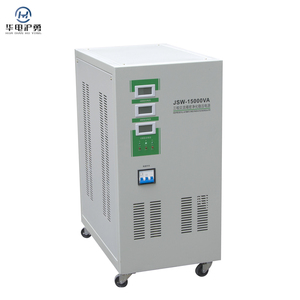
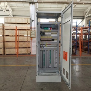
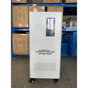
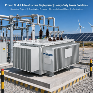
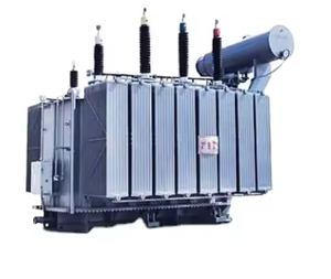
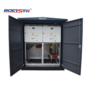
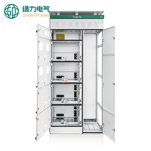
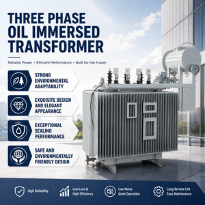
Modern electrical networks demand far more than legacy stepped core transformations. As heavy industries integrate renewable generation, mega-scale data processing facilities, and non-linear power electronic loads, the electrical stresses on Medium Voltage (MV) transformers have intensified by orders of magnitude. The contemporary MV transformer operates as an active barrier against harmonic resonance, thermal surges, and severe dielectric breakdown.
As an industry-leading manufacturer and global exporter, our engineering philosophy bridges precision electromagnetic design with robust mechanical architecture. Utilizing laser-scribed Cold-Rolled Grain-Oriented (CRGO) silicon steel or advanced amorphous metal formulations, our medium-voltage solutions achieve ultra-low no-load core losses while dampening excitation magnetizing currents. From 10kV compact secondary distribution networks to 115kV transmission interfaces delivering up to 60 MVA, our systems are optimized for zero unscheduled downtime across multi-decade lifecycle spans.
Backed by 35 years of industrial automation and panel engineering heritage since 1990, every magnetic core and winding assembly conforms to zero-defect standards.
Engineered with Class F, H, or Class C vacuum-pressure impregnated (VPI) and vacuum cast epoxy resin insulation. For liquid-immersed topologies, we offer high flash-point synthetic and natural ester liquids to reduce fire hazard exposure in dense urban and offshore environments.
With massive deployments of Variable Frequency Drives (VFDs) and non-linear rectifiers in modern plants, our winding topologies utilize electro-static shielding and stepped foil windings to dissipate eddy current losses, preventing hot-spot degradation and insulation failure.
Every medium voltage unit undergoes comprehensive computerized validation before dispatch: Double Voltage Double Frequency (DVDF) testing, insulation resistance testing (Megger), winding resistance via milli-ohm bridges, and infrared thermal imaging under simulated overload states.
Detailed comparison of primary topology configurations available for international infrastructure tenders.
| Parameter / Specification | Cast Resin Dry-Type MV Transformer | Fully-Sealed Oil-Immersed MV Transformer | Pad-Mounted Utility Substation Transformer |
|---|---|---|---|
| Rated Capacity (kVA / MVA) | 100 kVA to 25,000 kVA | 50 kVA up to 60 MVA | 50 kVA to 5,000 kVA |
| Primary Voltage Class | 3.3 kV, 6.6 kV, 11 kV, 22 kV, 33 kV, 35 kV | Up to 115 kV (Custom up to 220 kV) | 4.16 kV up to 34.5 kV (Loop/Radial Feed) |
| Cooling System Standards | AN (Air Natural) / AF (Air Forced) | ONAN / ONAF / OFAF (Mineral or Bio-Ester) | KNAN / ONAN (Dead-front security design) |
| Environmental / Fire Class | F1 / E2 / C2 (Self-extinguishing, zero toxic gases) | Outdoor heavy industrial, requires catchment berm | Tamper-resistant, outdoor public installation (NEMA / IEEE) |
| Routine Type Validation | Partial Discharge < 10 pC, Lightning Impulse, DVDF | Dissolved Gas Analysis (DGA), Dielectric Breakdown | Short-circuit withstand, temperature-rise test (IEC 60076) |
| Primary Target Application | Underground subways, data centers, offshore vessels | Generation substations, steel mills, utility grids | Commercial real estate, solar farms, industrial parks |
The global medium-voltage transformer supply chain is experiencing profound transformations driven by grid decarbonization, aging infrastructure replacement across North America and Europe, and the explosive power demands of artificial intelligence compute centers. Global procurement executives and lead power engineers must navigate critical procurement shifts:
Critical criteria procurement managers and technical auditors should verify before issuing international Letters of Credit (L/C).
Ensure precise synchronization between incoming medium voltage supply and site switchgear (e.g., Dyn11 vs. YNd11). Incorrect vector group selection can prevent parallel transformer operation and introduce catastrophic circulating currents across secondary busbars.
Insist on short-circuit dynamic withstand calculation reports validated in accordance with IEC 60076-5. The core clamping system, axial pre-stressing rings, and lead bracing must withstand maximum prospective electromagnetic forces during secondary fault scenarios.
Evaluate initial capital expenditure against capitalized losses over a 25-year service window. A lower-priced transformer with higher no-load core losses frequently costs 200% to 300% more in lifetime operational energy overhead than a premium, optimized core unit.
Detailed answers to direct questions submitted by international EPC contractors and plant directors.
Consult directly with our medium-voltage electrical application engineers to obtain guaranteed dimensional layouts, loss calculations, and competitive FOB/CIF quotation terms for your project.
Send an Inquiry