 CEMarked CEMarked
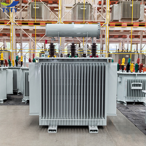
Engineered for renewable grid injection, high-power automation drives, heavy industrial substations, and severe hazardous conditions. Directly audited and verified for low losses, elevated thermal withstand, and long-term operating durability.
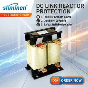
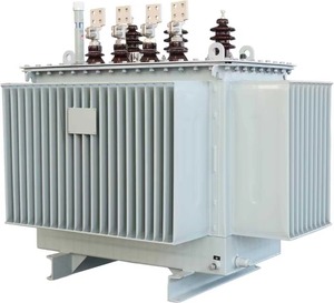
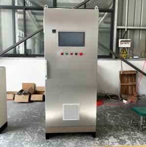
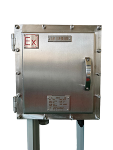
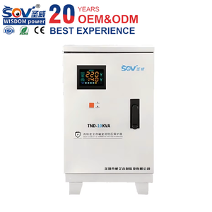
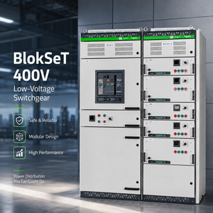
Originating from an automation engineering powerhouse established in 1990, our transformer manufacturing ecosystem solves electrical conversion challenges from the viewpoint of control panel builders, utility contractors, and global OEMs. Having engineered PLC/SCADA systems, variable frequency drive infrastructure, and ATEX/IECEx hazardous-environment enclosures for decades, we integrate deep electromagnetic insight directly into every step-up transformer design.
Operating out of our expansive 5,500 m² heavy-industrial manufacturing plant in Santej, Ahmedabad, our facility combines automated high-tension winding, vacuum pressure impregnation (VPI), core precision stacking with cold-rolled grain-oriented (CRGO) silicon steel, and automated oil purification. Every export transformer carries full CE marking and complies rigorously with IEC 60076, IEEE C57.12, and ISO 9001/14001 frameworks.
Every single step-up and distribution transformer undergoes comprehensive in-house computerized verification before shipping clearance. Factory Acceptance Test (FAT) dossiers are issued per IEC 60076:
A step-up transformer converts alternating current (AC) from a lower voltage potential to a significantly higher voltage level while inversely stepping down current proportionally. In utility generation, renewable energy farms, and high-load transmission, stepping up voltage reduces transmission $I^2R$ resistive heating losses, enabling compact cable cross-sections and long-distance transport efficiency.
The efficiency of a high-capacity step-up transformer depends directly on core excitation performance. We employ prime-grade, domain-refined laser-scribed Cold-Rolled Grain-Oriented (CRGO) magnetic silicon steel sheets (0.23mm to 0.27mm laminations). Mitred 45-degree step-lap joints minimize eddy current turbulence, flux leakage, and audible magnetostrictive hum.
Step-up applications demand massive thermal withstand capability and high mechanical rigidity during short-circuit electromagnetic stress. Primary low-voltage windings are engineered with continuous transposed conductor (CTC) or electrolytic copper foil to eliminate axial forces, while high-voltage windings feature disc or interleaved continuous winding topologies.
Continuous loading in industrial step-up transformers (such as solar inverter stations or generator bus connections) generates localized winding hot spots. Our engineering accounts for exact thermal dissipation curves via Oil Natural Air Natural (ONAN), Oil Natural Air Forced (ONAF), or dry-type forced ventilation (AF).
| Transformer Architecture | Primary Voltage (LV) | Secondary Voltage (HV) | Capacity Spectrum | Target Industrial Application |
|---|---|---|---|---|
| Generator Step-Up (GSU) Oil-Immersed | 0.4kV / 0.69kV / 3.3kV / 6.6kV | 10kV / 20kV / 33kV / 35kV | 500 kVA to 5000 kVA | Hydroelectric stations, gas turbine generators, centralized utility plants |
| Solar PV & BESS Dual-Winding Step-Up | 0.6kV / 0.8kV AC inverter outputs | 11kV / 22kV / 33kV / 34.5kV | 1000 kVA to 4000 kVA | Utility-scale solar farms, grid-tied battery energy storage systems |
| Cast Resin Dry-Type Step-Up (CRT) | 400V / 480V / 600V | 6.6kV / 10kV / 11kV / 20kV | 100 kVA to 3150 kVA | Offshore platforms, chemical plants, underground substations, commercial hubs |
| Industrial Variable Autotransformer | Custom LV (110V - 415V) | Stepped Ratio / Boosted Output | 50 VA to 1000 kVA | Industrial machinery testing, laboratory calibration, voltage boosting lines |
| Heavy-Current VFD Drive Converter Transformer | 0.4kV / 0.69kV / 1.1kV | Phase-shifted multi-pulse LV/MV | 500 kVA to 3500 kVA | 12-pulse, 18-pulse, 24-pulse VFD drives, rolling mills, mining excavators |
Global decarbonization initiatives, grid volatility, and supply chain re-shoring have radically transformed procurement strategies. Strategic EPC contractors and purchasing directors prioritize future-proof specifications over baseline initial capital expenditure.
Modern step-up transformers must withstand non-sinusoidal harmonic loading from IGBT solar inverters and bidirectional active/reactive power swings from utility-scale Battery Energy Storage Systems (BESS), requiring dedicated K-factor ratings (K-9, K-13) and multi-split low-voltage coils.
Stringent environmental standards are pushing EPCs toward synthetic and natural ester dielectric liquids (fire point > 300°C, K3 class). Ester-filled transformers reduce insurance premiums, eliminate mandatory concrete containment bunds, and offer 100% biodegradability in sensitive zones.
European Ecodesign (Tier 2) and global minimum energy performance standards (MEPS) mandate optimized capitalized loss calculations: $TCO = Purchase\ Price + A \times P_o + B \times P_k$. Low-loss transformers recoup premium purchase costs within 24 to 36 months through continuous kilowatt-hour savings.
Procurement bids increasingly require integrated fiber-optic hot-spot sensors, dynamic electronic temperature controllers, continuous moisture-in-oil analyzers, and Modbus/IEC 61850 communication cards, turning transformers into smart IoT grid nodes capable of predictive maintenance.
Overcoming the challenges of harmonic distortion, thermal saturation, and seismic vulnerabilities through advanced material engineering and precision fabrication.
In addition to conventional CRGO cores, Chinese and Indian manufacturing facilities are standardizing on amorphous metal alloys for low-load step-up applications. By cooling rapidly during molten ribbon processing, amorphous metal lacks crystalline structure, diminishing core excitation hysteresis by over 70% compared to traditional grade silicon steel.
This leap is especially critical for intermittent energy generation facilities (such as solar farms during night-time standby), preventing idle transformer vampire drain across massive distribution arrays.
For chemical corridors, urban commercial towers, marine vessels, and confined tunnels where oil fires pose catastrophic liability, cast resin dry-type technology has surged in capability. Windings are completely encapsulated under vacuum in fiberglass-reinforced pure epoxy resin (Class F 155°C or Class H 180°C).
This renders the core-and-coil assembly non-hygroscopic, self-extinguishing, maintenance-free, and thoroughly impervious to tropical humidity, conductive dust, and coastal salt-spray contamination.
Coupling transformers directly to high-frequency pulse-width modulated (PWM) inverter outputs subjects insulation to repetitive high $dv/dt$ voltage gradients, causing partial discharges. Advanced electrostatic shielding placed between primary and secondary windings drains common-mode capacitive high-frequency currents safely to earth.
Combined with specialized DC smoothing chokes and sine-wave harmonic filters, this protects motor windings, suppresses reflected waves, and guarantees high power quality compliance at grid coupling points.
Our engineering team delivers full electrical design verification, vector group customization, short-circuit withstand validation, and prompt technical quotations conforming to your exact tender specifications.
Get a QuoteClear, definitive technical clarifications addressing sizing, installation, compliance, and custom manufacturing constraints.
From an electromagnetic standpoint, transformers are reciprocal machines: passing power in either direction functions under the law of electromagnetic induction ($V_p/V_s = N_p/N_s$). However, a transformer specifically manufactured for step-up service is engineered with critical physical differences:
1. Tapping Arrangement: Taps are typically located on the high-voltage winding where current is lower, facilitating safer, more durable off-circuit or on-load tap changer design.
2. Inrush Current Tolerance: The low-voltage primary experiences massive magnetizing inrush current (often 8 to 12 times rated current). Core design, clamp rigidity, and primary winding cross-sections are substantially reinforced to resist high electromagnetic shear forces.
3. Insulation Grading & Vector Groups: Step-up units feeding transmission lines usually employ YNd11 or Dyn11 vector groups to establish an effectively grounded neutral system on the secondary high-voltage side, trapping zero-sequence third harmonics within the delta winding.
While reverse-feeding a standard step-down transformer is physically possible in small emergency low-voltage tasks, it creates serious operational vulnerabilities in industrial applications:
• Voltage Drop Compensation: Standard step-down units feature a compensated turns ratio (typically engineered with a 2.5% to 5% voltage boost on the secondary to offset internal impedance drops under load). Reverse-feeding causes an immediate negative output voltage deficit.
• Excitation Flux Saturation: Energizing what was designed as the inner secondary winding can lead to core over-excitation, causing severe overheating, excessive harmonic distortion, and nuisance tripping of protection relays.
• Tap Changer Inversion: Tap changer positions become mathematically inverted, complicating voltage regulation.
To produce an authoritative, optimized engineering quote, please provide the following technical parameters:
1. Rated Capacity: Rated kVA or MVA capacity under continuous thermal operation.
2. Voltage Specifications: Nominal primary voltage, secondary voltage, and required tapping range (e.g., ±2×2.5% OCTC or OLTC).
3. Frequency & Phases: 50 Hz or 60 Hz; Single-phase or Three-phase.
4. Vector Configuration: Vector group (e.g., Dyn11, YNd11, YNyn0, etc.).
5. Cooling Mode & Dielectric: ONAN, ONAF, AN, AF; High-grade mineral oil or eco-friendly ester fluid.
6. Short-Circuit Impedance (%Z): Standard or custom impedance percentage required for short-circuit level coordination.
7. Ambient & Installation Environment: Altitude above sea level (if >1000m), maximum ambient temperature, seismic zone, and indoor/outdoor IP enclosure rating.
Our manufacturing protocols and finished magnetic products strictly adhere to the world's most rigorous regulatory and technical standards:
• IEC 60076: Parts 1 to 5 (Power Transformers - general, temperature rise, dielectric tests, short-circuit withstand).
• IEEE / ANSI C57.12: Standard requirements for liquid-immersed and dry-type distribution, power, and regulating transformers.
• European Directives: CE Marking compliance across the Low Voltage Directive (LVD) and Machinery Directive.
• Hazardous Atmospheres: ATEX and IECEx compliance for associated explosion-proof control cabinets, purge systems, and junction distribution enclosures.
• Quality Auditing: Certified under ISO 9001 (Quality Management), ISO 14001 (Environmental Stewardship), and ISO 45001 (Occupational Health & Safety).
Export packaging is engineered to withstand extreme marine conditions, multi-port handling, and long-term storage in tropical climates. All finished transformers receive heavy vacuum-sealed foil vapor wraps containing moisture-indicating desiccant bags.
External enclosures and heavy transformer bodies are fastened to fumigated, heat-treated ISPM-15 wooden skids or heavy structural steel transport bases. Bushings and fragile instruments (Buchholz relays, magnetic oil level gauges, winding temperature indicators) are protected by custom steel transport frames or dismantled and packed into dedicated shock-proof internal timber crates with continuous tilt and impact monitoring sensors affixed.
Whether you are engineering a high-voltage utility connection, retrofitting an industrial drive array, or procuring step-up units for international EPC contracts, our senior magnetics design team is prepared to review your single-line diagrams (SLD) and tender schedules.