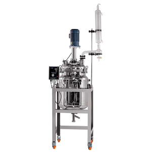
Single & Double Layer Jacketed Stainless Steel Process Reactor
Scalable 1L to 500L stainless vessels designed for thermal reaction control, pilot plants, and continuous mechanical mixing.
 CEMarked
Engineered to dampen high-frequency pulse-width modulated (PWM) voltage peaks, lower thermal stress on induction motors, and ensure long cable operational stability.
Scalable 1L to 500L stainless vessels designed for thermal reaction control, pilot plants, and continuous mechanical mixing.
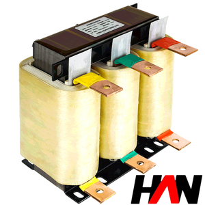
Heavy-duty AC choke suppressing THD-i emissions, protecting variable speed drive front-end rectifiers, and optimizing power factors.
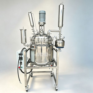
Engineered for controlled laboratory synthesis, vacuum reflux cycles, and demanding petrochemical pilot operations.
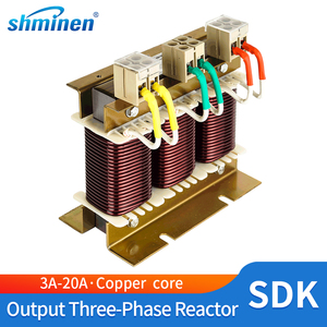
High-speed switching inverter motor drive choke designed for low-power automation, limiting insulation surge degeneration.
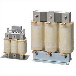
Direct OEM-compatible drive inductive filter engineered to suppress high dv/dt reflections along long motor cabling runs.
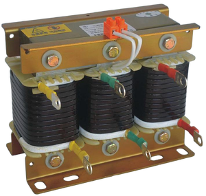
Prevents capacitor resonance, eliminates harmonic amplification, and stabilizes plant-wide reactive power factor panels.
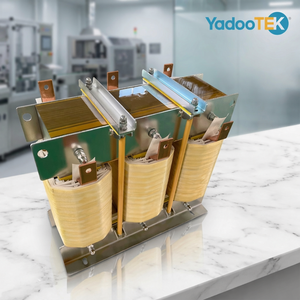
Broadband high-capacity magnetic design tailored for severe duty manufacturing, mining pumps, and conveyor drives.
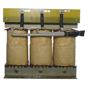
Rugged copper-wound design providing high thermal headroom and extended bearing life across automation lines.
A rigorous examination of voltage reflections, standing waves, and inductive impedance mitigation in modern IGBT-driven motor systems.
The dv/dt Phenomena Explained: Modern Variable Frequency Drives (VFDs) utilize Insulated Gate Bipolar Transistors (IGBTs) switching at frequencies between 2 kHz and 16 kHz. This ultra-fast rise time (<0.1 microseconds) produces steep dv/dt voltage wave fronts that propagate down motor lead cables, causing transmission-line reflections that double the operational voltage applied to motor stator windings.
When cable length exceeds the critical distance (typically 15 to 30 meters), impedance mismatch causes voltage wave reflections. A precision CE-certified output reactor provides the necessary series inductive impedance (1.5%, 3%, or 5% impedance rating) to smooth out microsecond edge rates, holding peak phase-to-phase and phase-to-ground voltages within IEC/NEMA MG1 Part 31 insulation thresholds.
High-frequency current spikes cause continuous dielectric stress, micro-arcing in winding insulation, and severe thermal buildup. Integrating an engineered output line reactor dampens high-frequency harmonic content, keeping motor operating temperatures 10°C to 20°C cooler and doubling insulation dielectric life expectancy.
Common-mode voltages induced across drive rotor shafts result in Electrical Discharge Machining (EDM) currents through motor bearings, creating destructive fluting, mechanical pitting, and premature mechanical bearing failure. Output reactors provide substantial common-mode attenuation across industrial PWM spectrums.
| System Architecture Requirement | Standard Cable Run (<30m) | Extended Cable Run (30m - 150m) | Critical Extreme Run (>150m - 1000m) |
|---|---|---|---|
| Primary Protective Device | Direct Connection / 1.5% Line Reactor | 3% - 5% CE Output Line Reactor | LC Sine Wave Filter / dv/dt Filter |
| Peak Voltage at Motor Terminals | <1.2 × V_bus (Controlled) | Clamped to <1.6 × V_bus | Fully Restored Sine Wave (<1.05 × V_bus) |
| Current THD Reduction | Marginal System Distortion | 15% - 25% High Frequency Damping | >85% Harmonic Elimination (<5% THD) |
| Audible Motor Noise | Standard High-Pitch PWM Noise | Significantly Dampened Audible Choke | Near Silent Pure Sine Operation |
| Total System Capital Cost | Baseline Economy | Optimal Cost/Protection Equilibrium | High Capital Investment |
How Silicon Carbide (SiC) converters, renewable microgrids, and rigorous carbon standards are reshaping industrial magnetic purchasing parameters.
Next-generation motor drives are transitioning rapidly from traditional silicon IGBTs to Silicon Carbide (SiC) and Gallium Nitride (GaN) switching topologies. Operating at switching frequencies above 50 kHz with rise times sub-10 nanoseconds, these systems generate destructive dv/dt spikes. Forward-thinking procurement teams require line reactors engineered with ultra-low core loss nanocrystalline and amorphous magnetic formulations to withstand high switching frequencies.
As international regulators expand carbon taxation and enforce higher minimum efficiency performance standards (MEPS), passive electrical components are under closer scrutiny. Future output reactors require grain-oriented silicon electrical steel (CRGO) cores with precision step-lap mitered joints and Class H/C (180°C/200°C) vacuum pressure impregnated (VPI) insulation, curbing no-load stray losses while lowering operational carbon metrics.
With distributed wind generation, utility solar, and localized battery energy storage systems (BESS) feeding non-linear inverter currents into fragile plant substations, multi-tapped line reactors will become standard. Procurement engineers are prioritizing modular reactor chassis featuring plug-and-play auxiliary sensing coils that stream temperature and magnetic saturation telemetry directly to plant SCADA interfaces.
Combining over 25 years of specialized automation panel manufacturing with advanced 5,500 m² computerized transformer fabrication.
Founded on decades of engineering expertise via parent company Prima Automation (India) Pvt. Ltd., crafting certified PLC, SCADA, and hazardous-area panels since 1990.
Located in Santej, Ahmedabad, our facility operates high-speed automated foil and wire winding machinery, automated vacuum drying, and continuous VPI resin impregnation systems.
Every single unit undergoes automated open-circuit/short-circuit testing, Double Voltage Double Frequency (DVDF) induced overvoltage tests, and digital LCR inductance validation.
Full CE certification ensures direct compliance across European, Middle Eastern, and North American industrial integration frameworks, serving over 45 major industrial conglomerates.
Trusted Partner to Industry Leaders: Supplying customized magnetic solutions to Jindal, Tata, UltraTech Cement, ONGC, Adani, Suzlon, Vedanta, and Siemens-partner automation integrators.
Crucial answers to assist industrial project engineers, system integrators, and international procurement managers.
While both devices consist of three-phase iron or air-core series inductors, their electrical functions differ based on circuit location. An Input Line Reactor is connected between the utility power supply and the VFD's input rectifier. Its primary mission is absorbing mains surges, lightning line transients, reducing low-frequency harmonics (3rd, 5th, 7th harmonic current components), improving overall power factor, and shielding the front-end diode bridge. Conversely, an Output Load Reactor is installed between the VFD inverter terminals and the motor. It handles high-frequency PWM switching pulses, lowers dv/dt voltage gradients, reduces cable charging currents on long lead runs, and limits peak overvoltages at motor windings.
The percent impedance refers to the percentage of total system nominal voltage dropped across the reactor at rated full-load fundamental current. A 3% impedance reactor is standard for typical factory installations where motor cable leads extend between 30 and 75 meters. It delivers dependable motor spike protection with negligible line voltage attenuation. A 5% impedance reactor is recommended when motor cabling exceeds 75 meters, up to approximately 150 meters, or when multiple motors run in parallel from a single drive output. A 5% choke delivers superior harmonic dampening, though it creates a higher voltage drop under peak industrial load conditions.
Within our Santej manufacturing plant, all line and load reactors undergo comprehensive quality screening via computerized test panels: (1) Digital LCR Verification to test inductance symmetry balance across all three individual phases; (2) Milli-Ohm DC Winding Resistance Measurement to verify conductor consistency; (3) Double Voltage Double Frequency (DVDF) induced overvoltage testing to confirm inter-turn insulation reliability; (4) High-Potential (Hi-Pot) Dielectric Strength Test to detect leakage between coils and ground cores; (5) Insulation Resistance (Megger) Testing at 1000V/2500V; and (6) Infrared Temperature Rise Characterization under controlled inductive load conditions.
For installations where drive-to-motor cable lengths surpass 150 meters (typical in deep-well submersible pumps, mining vent fans, oilfield extraction, and offshore cranes), standing wave reflection and high capacitive charging current cannot be entirely smoothed by a simple series output line reactor alone. In such situations, installing a Sine Wave Filter—which integrates low-pass LC inductive coils and power capacitors—is essential. Sine wave filters strip out the high-frequency PWM carrier completely, delivering a smooth sinusoidal voltage to the motor terminals and eliminating transmission-line reflections over runs exceeding 1,000 meters.
To prepare an accurate engineering drawing and quotation within 24 hours, our design department requires: (1) VFD motor power capacity (kW or HP); (2) Nominal operating system voltage (e.g., 380V, 415V, 480V, 690V) and frequency (50/60 Hz); (3) Rated continuous motor current (Amperes); (4) Desired impedance level (typically 1.5%, 3%, or 5%); (5) Total cable distance between inverter and motor; (6) Drive carrier/switching frequency setting (kHz); (7) Enclosure protection tier (Open frame IP00, or ventilated IP20, IP23, IP54 steel cabinet); and (8) Environmental ambient parameters (e.g., elevated ambient operating temperatures up to 55°C).
Connect with our senior magnetic application engineers for full technical reviews, custom drawings, and competitive export pricing for worldwide panel projects.
Send an Inquiry