CEMarked CEMarked
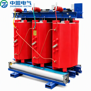
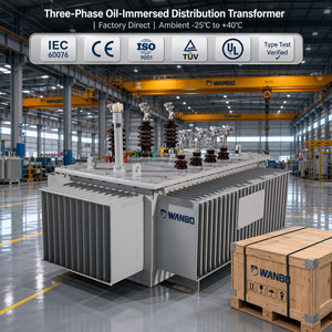
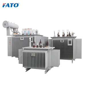
Explore our core engineering catalog spanning high-attenuation line/load reactors, dry-type resin transformers, and heavy-duty distribution units engineered for demanding global export standards.
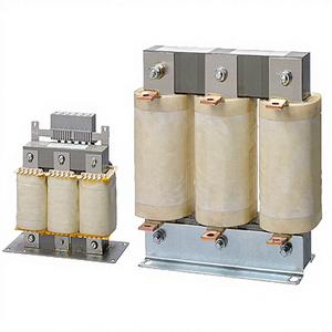
Modern industrial automation relies fundamentally on Variable Frequency Drives (VFDs) and variable speed control architectures to maximize process precision and electrical efficiency. However, the three-phase six-pulse rectifier bridge inherently configured at the front end of traditional and regenerative VFDs presents an intensely non-linear load profile to upstream electrical power networks. During operation, current flows through the rectifier diodes into the DC link bus capacitor bank only when the instantaneous line-to-line AC supply voltage surpasses the direct-current capacitor voltage. This discontinous, pulsed conduction mechanism produces severe current distortion rich in the 5th, 7th, 11th, and 13th harmonic orders.
Without adequate inductive reactance installed on the feeder side, Total Harmonic Current Distortion ($THD_i$) at the drive terminals routinely exceeds 80% to 120%. Such unregulated harmonic injection degrades the entire upstream electrical distribution system, causing significant transformer core saturation, excessive neutral conductor overheating, premature power factor correction capacitor dielectric breakdown, and destructive notch depths on the supply voltage waveform ($THD_v$).
Beyond steady-state harmonic mitigation, three-phase input AC reactors serve as high-integrity physical energy buffers protecting sensitive semiconductor components. Utility grid switching phenomena—such as high-voltage power factor correction capacitor bank switching, inductive load interruption, or distant lightning strikes—produce steep-fronted voltage transients with rise times measured in nanoseconds. Unbuffered drive converters experience catastrophic DC link overvoltage trips, diode bridge puncturing, and surge suppressor (MOV) exhaustion.
An inductive line reactor acts as a low-pass filter to high-frequency transients, limiting the maximum rate of current rise ($di/dt$). By converting rapid transient energy into momentary electromagnetic flux within the laminated grain-oriented silicon steel core, the input reactor guarantees that line-side surges are clamped before reaching the sensitive inverter electronics, drastically increasing Mean Time Between Failures (MTBF) for mission-critical industrial assets.
Specifying the proper percentage impedance (%Z) represents the single most crucial engineering decision in the input reactor procurement workflow. Nominal impedance signifies the percentage of rated line voltage dropped across the reactor windings at full load rated current:
| Impedance Class | Nominal THDi Reduction | Voltage Drop at Rated Load | Primary Industrial Application Context | IEEE 519 Compliance Contribution |
|---|---|---|---|---|
| 1.5% to 2.0% Impedance | Reduces $THD_i$ to ~45% - 55% | 1.5% - 2.0% nominal RMS | Extremely stiff grids with localized DC link chokes already inside the VFD; minimal footprint panels. | Low baseline mitigation; requires secondary filtering. |
| 3.0% Impedance (Standard) | Reduces $THD_i$ to ~35% - 40% | 3.0% nominal RMS (approx. 11.4V on 380V) | Standard industrial motor control centers (MCC), pump stations, HVAC fans, and plant processing lines. | Moderate; standard for internal plant harmonic attenuation. |
| 5.0% Impedance (High Attenuation) | Reduces $THD_i$ to ~28% - 33% | 5.0% nominal RMS (approx. 19.0V on 380V) | Substations near utility cap banks, weak/generator networks, cross-talk mitigation, and heavy industrial cranes. | High; provides optimal attenuation without active electronic filters. |
While a 5% reactor yields substantially superior harmonic suppression and transient dampening, the designer must account for the corresponding 5% fundamental voltage reduction experienced by the inverter input under full continuous load. If the utility voltage sits persistently below nominal (e.g., 360V on a nominal 400V line), a 5% drop can induce drive under-voltage faults during maximum torque acceleration demands. Our engineering team calculates winding turns, copper cross-sections, and core air-gaps to deliver precisely specified impedance tolerance bands under real-world operating temperatures.
Prima Transformers Pvt. Ltd., incorporated in 2006 as a 100% subsidiary of Prima Automation (India) Pvt. Ltd., manufactures industry-benchmark power quality magnetics from a cutting-edge 5,500 m² facility located in Santej, Ahmedabad, Gujarat, India. Our engineering heritage traces directly back to 1990 through our parent organization’s extensive design of PC, PLC, and SCADA-based automation panels, including pressurized, explosion-proof, and intrinsically safe control switchgear for hazardous industrial environments.
This distinct automation panel-builder perspective directly informs how every input AC reactor is manufactured. We do not design magnetics as isolated laboratory components; we engineer them specifically to survive the thermal, mechanical, and electromagnetic rigors of dense industrial electrical enclosures.
We utilize precision cold-rolled grain-oriented (CRGO) silicon steel laminations (Grade M6 or better) with optimized multi-stepped air-gap distribution to prevent localized magnetic fringe heating and acoustic buzz under heavy harmonic current loading.
Every reactor undergoes multi-cycle high-vacuum pressure impregnation (VPI) with Class H solventless epoxy varnish, baked in computerized curing ovens. This eliminates micro-voids, locks out moisture, and guarantees silent, vibration-free operation under cyclic stress.
Products strictly satisfy the European Union Low Voltage Directive 2014/35/EU, EN 61558-2-20, and IEC 60076-6 standards. Every unit is audited via automated computerized test benches for open/short circuit, DVDF, LCR inductance, and insulation resistance prior to dispatch.
To provide ironclad reliability for global export partners, our dedicated quality assurance lab subjects 100% of manufactured units to rigorous routine testing in accordance with international standards before packaging and shipping:
The global industrial magnetic and inductive filter market is undergoing transformative shifts driven by three primary technological catalysts: the proliferation of Wide Bandgap (WBG) semiconductors, aggressive decarbonization mandates demanding lower magnetic core losses, and the migration of global supply chains toward dependable multi-region manufacturing hubs.
Silicon Carbide (SiC) and Gallium Nitride (GaN) active front ends (AFE) switch at frequencies upwards of 20 kHz to 50 kHz. Traditional coarse steel laminations suffer massive eddy current losses at these harmonics. Future line reactors increasingly adopt ultra-thin gauge (0.18mm - 0.23mm) high-silicon steels and amorphous alloy cores to retain exceptional inductance linearity without severe thermal penalties.
European and North American procurement protocols are transitioning from initial purchase price valuation to lifetime Total Cost of Ownership (TCO). High-efficiency input reactors designed with oversized electrolytic copper conductors, optimized cross-sectional foil geometries, and sub-1.2 W/kg core materials drastically cut recurring kilowatt-hour energy waste over 15-year factory life cycles.
Modern process plants demand continuous operational visibility. Forward-looking input AC reactors integrate factory-embedded PT100 RTDs or digital Modbus-enabled thermal sensing probes within the center coil winding. This enables edge-level predictive maintenance software to track harmonic overload, ambient temperature spikes, and impending cooling degradation before unscheduled shutdowns occur.
Engineering procurement managers throughout Europe, the Americas, and the Middle East are actively diversifying their supplier portfolios to counter single-source vulnerability, volatile logistics, and rising geopolitical tariffs. India has emerged as the premier manufacturing alternative, providing a highly developed metallurgical engineering infrastructure, a deep pool of skilled electrical winding labor, and competitive manufacturing economics.
Prima Transformers embodies this strategic advantage: combining world-class Indian production scalability in our 5,500 m² facility with uncompromising CE, IEC, and UL-aligned quality systems. Our global export division provides comprehensive export crating (ISPM-15 heat-treated maritime timber), multi-voltage flexibility (208V, 380V, 415V, 480V, 600V, 690V), and fully computerized factory acceptance test documentation dispatched with every consignee lot.
Expert answers to critical engineering, installation, and procurement questions from industrial system integrators and OEM panel builders.
While both devices are magnetic inductors, their placement within the drive circuit defines their specific functional duties:
IEEE 519 establishes strict limits on the maximum allowable Total Demand Distortion (TDD) and voltage harmonic distortion ($THD_v$) at the Point of Common Coupling (PCC) between the industrial consumer and the electric utility. A standard six-pulse variable speed drive with zero inductance exhibits current distortion exceeding 80%. By integrating an engineered 3% or 5% input AC line reactor, current distortion is suppressed to approximately 30% to 35%. While very stringent IEEE 519 targets on weak electrical grids may ultimately necessitate active harmonic filters or multi-pulse configurations, a 5% AC reactor provides the most cost-effective first line of defense, often bringing medium-sized industrial plants into immediate compliance without complex active electronics.
Both materials offer distinct operational and economic advantages when engineered correctly. Electrolytic High-Conductivity Copper (ETP Grade) features lower electrical resistivity, requiring smaller cross-sectional winding volumes. This results in an exceptionally compact overall physical footprint, reduced weight, and superior heat conduction, making it the gold standard for dense OEM control panels. Grade EC Aluminum offers an outstanding weight-to-performance ratio and lower initial capital cost for larger ratings (above 400A), though it demands larger physical core windows and enclosure dimensions to compensate for aluminum’s lower ampacity. Prima Transformers engineers both high-conductivity copper and aluminum wound reactors with vacuum-impregnated insulation to deliver identical thermal rise and electrical performance envelopes.
Magnetic core saturation occurs when the magnetic flux density ($B$) inside the silicon steel core reaches its upper physical limit, causing the core permeability ($\mu$) to collapse toward that of air. When an inductor saturates, its inductance drops precipitously, losing its current-limiting capability. During heavy motor starting surges, momentary short-circuit transients, or aggressive dynamic braking (where inrush currents can easily reach 150% to 200% of nominal rating), an improperly designed reactor saturates, exposing the drive's rectifier diodes to unchecked fault energy. Prima Transformers designs its reactors with multi-segmented air gaps and generous magnetic flux margins to ensure full linearity (no more than 10% inductance drop) up to 200% of rated operating current.
To ensure a rapid and technically accurate quotation from our application engineering division, please provide the following technical parameters:
Leverage 25+ years of Indian manufacturing excellence, complete CE certification compliance, and engineering-grade custom design capabilities for your VFD, drive panel, and power quality projects.