Santej, Ahmedabad, Gujarat, IndiaCE-Marked Transformers for Export
Serving OEMs & Projects Worldwide
CEMarked
CE Certified Industrial Control Transformer Supplier & Exporter
Precision-Engineered Low & Medium Voltage Power Transformation Solutions Built for Rigorous Automation, VFD Drives, and Heavy Industrial Plant Environments Worldwide.
Factory Direct Catalog
Engineered Industrial Transformers & Distribution Units
Standard and custom electromagnetic assemblies designed in our 5,500 m² high-tech manufacturing plant, carrying complete CE mark conformity for heavy industrial export.
Industrial Automation DNA & Advanced Manufacturing Strength
Operating as an elite manufacturing powerhouse in Santej, Ahmedabad, our facility combines automated coil winding, core stacking, vacuum pressure impregnation, and computerized testing under one certified roof.
Panel-Builder Heritage Since 1990
As a 100% subsidiary of Prima Automation (India) Pvt. Ltd., our core engineering is built on 35+ years of practical switchgear and control panel construction. We understand inrush current spikes, contactor coil dropouts, heat dissipation, and spatial restrictions inside PLC and MCC enclosures better than conventional transformer winders.
Stringent In-House Testing Protocols
Every unit undergoes strict computerized routine testing before export: Double Voltage Double Frequency (DVDF) induced overvoltage validation, open-circuit & short-circuit computerized evaluation, Megger insulation resistance testing, milli-ohm winding resistance analysis, and digital LCR inductance checks for optimal electromagnetic safety.
Full CE Marking & Global Export Compliance
Our control, isolation, and cast resin transformers carry authentic CE marking complying with the Low Voltage Directive (LVD 2014/35/EU) and EN 61558-2-2 / EN 61558-2-4 standards. Supplying tier-one multinationals across Europe, the Americas, the Middle East, and Southeast Asia with custom-engineered primary and secondary taps.
In modern industrial process automation, control transformers (also referred to as Industrial Control Transformers or Machine Tool Transformers) perform a mission-critical role: stepping down incoming plant distribution voltages (such as 480V, 415V, or 400V) to isolated, stable control voltages (e.g., 230V, 120V, or 24V). These secondary circuits feed highly sensitive electromagnetic loads, including programmable logic controllers (PLCs), auxiliary relays, contactor coils, safety interlocks, solenoid valves, and indicator pilots.
Unlike standard general-purpose distribution transformers that experience relatively continuous, steady-state linear load profiles, an industrial control transformer operates under severe transient conditions. When inductive electromagnetic actuators—most notably magnetic motor starters and high-current contactor coils—are first energized, they present an instantaneous inrush load (inrush VA) that is typically 300% to 1000% (3x to 10x) higher than their steady-state sealed holding VA. Failure to select a control transformer capable of managing this instantaneous peak will cause unacceptable secondary voltage dips, leading to contactor chatter, nuisance PLC resets, accelerated contact erosion, or system-wide interlocking failure.
The Engineering Formula for Transformer Sizing: Total Inrush VA Calculation requires summing the continuous holding VA of all continuously energized devices (relays, indicators, PLC power supplies, pilot lamps) and adding the single largest inrush VA of the most demanding contactor or solenoid that can be energized simultaneously.
Voltage Regulation Under Low-Power-Factor Inrush
During the millisecond-scale energization phase of a magnetic contactor coil, the power factor plummets to roughly 0.2 to 0.4 lagging. Under this low-power-factor state, internal transformer impedance induces high internal inductive voltage drop across the primary and secondary windings. Standard transformers suffer severe regulation droop, dipping output voltage below the critical 85% NEMA/IEC threshold where contactor armatures fail to seal cleanly.
Our CE certified industrial control transformers utilize ultra-low-loss grain-oriented silicon steel (CRGO) lamination cores and high-purity electrolytic copper windings with vacuum-pressure impregnation (VPI). By optimizing the magnetic coupling coefficient and decreasing internal leakage reactance, our transformers maintain output voltage well above 90% of nominal voltage even under a 400% sudden inrush transient, guaranteeing crisp armature pull-in and total operational reliability in mission-critical MCC/PCC panels.
Mitigating Variable Frequency Drive (VFD) Harmonics & dv/dt Transients
Modern industrial installations are dominated by pulse-width modulated (PWM) inverter drives. The non-linear rectifiers of variable speed drives inject severe harmonic distortion (predominantly 5th, 7th, 11th, and 13th orders) backward into plant distribution systems, elevating eddy current losses and skin effect resistance within transformer windings. Concurrently, fast-switching IGBT outputs produce steep high-frequency voltage rise times (dv/dt spikes exceeding 5,000 V/μs), creating reflective wave phenomena that stress downstream insulation.
To preserve power quality, our comprehensive magnetic product suite integrates coordinated Line and Load Reactors (rated up to 2500A) and tuned Sine Wave & Harmonic Filters (up to 500HP). Installed on the supply side, a 3% or 5% impedance line reactor suppresses harmonic currents, protects the drive bridge rectifier from utility voltage surges, and mitigates mains notch depth. On the load side, our reactors and sine wave filters reshape harsh PWM square waves into pristine sinusoidal profiles, eliminating cable dielectric puncture, reducing excessive motor bearing currents, and allowing motor cable runs exceeding 300 meters without external surge degradation.
Parameter / Dimension
Control Transformers (Single/Three Phase)
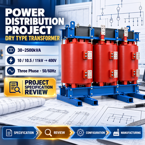
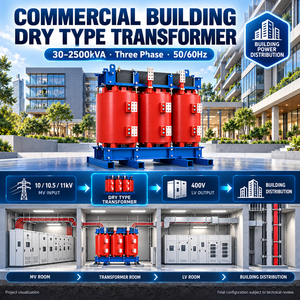
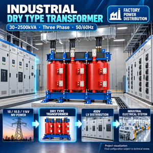
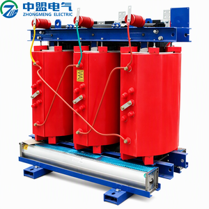
Cast Resin Dry Type Transformers
Line & Load Reactors
Standard Rating Range
50 VA to 50 kVA (Custom to 5000 kVA)
30 kVA to 2500 kVA (Custom to 5000 kVA)
Up to 2500 Amperes
Primary Voltage Options
110V, 208V, 230V, 400V, 415V, 480V, 690V
3.3 kV, 6.6 kV, 10 kV, 11 kV, 33 kV
200V – 690V AC, 50/60 Hz
Insulation Thermal Class
Class B (130°C), F (155°C), or H (180°C)
Class F (155°C) with Class H Hotspot
Class H (180°C) Standard
Dielectric Strength (Hi-Pot)
2.5 kV to 4.0 kV RMS / 1 minute
10 kV to 28 kV RMS / 1 minute
3.0 kV RMS / 1 minute
Core Material & Treatment
Cold-Rolled Grain Oriented (CRGO) M4/M5
Laser-treated CRGO / Silicon Steel
Low-Loss High-Flux Gapped Silicon Steel
Applicable Global Standards
IEC/EN 61558-2-2, 61558-2-4, CE, UL 508A
IEC 60076-11, EN 50541-1, CE Mark
IEC 60076-6, IEEE 519 Compliance
Enclosure Protection Degree
Open Type (IP00), Enclosed (IP20 to IP55)
IP00, IP21, IP23, IP31, IP54 Enclosures
Open Frame / IP20 Sheet Steel Louvered
Procurement Intelligence
Future Sourcing Trends for Industrial Transformers (2025–2030)
Strategic supply-chain considerations reshaping how global EPC contractors, automation OEMs, and plant procurement managers evaluate industrial magnetics.
Tier-3 Ecodesign & Energy Auditing Efficiency
Global decarbonization initiatives and stringent European Ecodesign directives (EN 50588-1 / EU 2019/1783) are pushing procurement teams away from baseline lowest-cost bids toward Total Cost of Ownership (TCO) models. Future tenders explicitly penalize no-load core hysteresis and load copper losses. Specifying ultra-low-loss core materials delivers operational payback within 18 to 36 months under continuous plant duty cycles.
Digital Twin & Smart IoT Integration Industry 4.0
Transformers are no longer static "fit-and-forget" magnetic blocks. Modern project specifications require direct integration with SCADA and industrial automation architectures. Procurement engineers are heavily prioritizing units factory-equipped with multi-channel PT100 temperature sensors, RS-485 Modbus telemetry, and continuous partial discharge tracking to enable AI-driven predictive maintenance and prevent catastrophic plant shutdowns.
International machine tool builders and panel exporters face severe lead-time volatility and divergent regional utility grids. The procurement trend favors modular, multi-tap primary configurations (e.g., universal 208V/230V/400V/460V/480V primaries) engineered on unified footprints. This enables OEM panel builders to manufacture a singular, standardized automation architecture capable of deploying effortlessly across worldwide export territories.
Technology Horizons
Technological Horizons in Industrial Power Magnetics
Engineering advancements driving the next generation of safe, high-density, and sustainable industrial transformers.
Non-Flammable Cast Resin & Biodegradable Esters
Stringent fire safety and environmental compliance within densely populated manufacturing parks, offshore platforms, and cleanroom facilities are driving rapid obsolescence of traditional mineral oil transformers. Cast resin epoxy formulation with self-extinguishing F1/E2/C2 certification and biodegradable synthetic ester fluids eliminate fire risks while neutralizing soil and groundwater contamination threats.
By replacing conventional crystalline silicon steel sheets with non-crystalline amorphous metallic glass ribbons, core eddy current and hysteresis losses are slashed by up to 70%. In light-load and intermittent automation cycles common to automated assembly lines and robotic packaging cells, amorphous core technology guarantees record electrical efficiency.
To combat severe AC copper skin and proximity effects induced by non-sinusoidal harmonic waveforms from multi-megawatt variable speed drives, coil engineering is shifting toward wide-aspect electrolytic copper foil winding. Foil geometry ensures optimal radial thermal dissipation, superior short-circuit mechanical strength, and minimal thermal hot-spots inside compact enclosure footprints.
Procurement Knowledgebase
Frequently Asked Questions for Technical Buyers & Importers
Direct technical answers from our senior design engineering team to accelerate your tender preparation and RFQ validation.
What parameters are essential to specify when requesting an industrial transformer quote?
To provide an exact, optimized engineering proposal, please specify: 1) Rated apparent power (VA, kVA, or MVA); 2) Primary and secondary rated voltages alongside required tapping percentages (e.g., ±2.5%, ±5%); 3) Operating frequency (50 Hz, 60 Hz, or universal 50/60 Hz); 4) Phase configuration and vector connection group (e.g., Dyn11, Yyn0); 5) Thermal insulation class (Class F or H) and permissible temperature rise; 6) Enclosure IP protection rating (IP00 open frame up to IP55 weatherproof/dustproof); 7) Duty cycle and any non-linear harmonic load details (K-factor or VFD presence).
What is the difference between a standard isolation transformer and an industrial control transformer?
While both provide galvanic isolation between primary and secondary windings to decouple control systems from utility line noise, an industrial control transformer is specifically engineered with very low internal inductive reactance and high momentary current overload capability. This ensures minimal secondary voltage drop (maintaining >90% voltage) during high-inrush, low-power-factor events when magnetic contactors and solenoid valves energize.
How does CE certification affect transformer construction and factory testing?
CE certification mandates rigorous compliance with European safety harmonized directives, predominantly the Low Voltage Directive (LVD 2014/35/EU) and relevant equipment standards EN 61558-1, EN 61558-2-2, and EN 60076. This mandates verified creepage and clearance distances, high-potential breakdown resistance (routine hi-pot dielectric tests exceeding 2.5–4.0 kV), Class F/H insulation thermal validation, and flame-retardant, non-toxic materials.
Why is Double Voltage Double Frequency (DVDF) testing critical for dry type units?
DVDF testing verifies the inter-turn, inter-layer, and inter-winding dielectric insulation of the transformer under exaggerated electromagnetic stress. By applying double the nominal working voltage at twice the operating frequency (e.g., 100 Hz or 200 Hz), we ensure the magnetic core does not saturate while validating that enamel coatings, Nomex barriers, and VPI resin cures have zero microscopic voids or shorted turns.
When should an engineer specify a line reactor versus an output load reactor on VFD drives?
A Line Reactor is installed on the AC utility supply side ahead of the VFD to protect the input diode bridge rectifier against power surges, lightning spikes, and transient capacitor switching while mitigating low-order current harmonics. An Output Load Reactor is installed between the VFD and the electric motor; its primary task is to attenuate high-frequency dv/dt voltage pulses, prevent insulation breakdown, and damp standing reflective waves on extended motor cabling.
What are your export packing and global logistics capabilities?
We supply OEMs, utility EPCs, and distributors across Europe, North America, Southeast Asia, and the Middle East. All units are vacuum sealed with moisture-absorbing desiccant barriers and packed inside treated, heavy-duty ISPM-15 compliant sea-worthy fumigated wooden crates. Complete documentation packages—including factory routine test reports, CE declaration of conformity, material traceability certificates, and warranty documentation—accompany every shipment.
Request an Engineered Quotation or Custom Transformer Design
Connect directly with our senior application engineering team in Santej, Ahmedabad. Whether you require custom multi-tap primary configurations, specialized dry-type enclosures, harmonic reactors, or complete substation transformers up to 5000 kVA, we deliver guaranteed performance tested to international standards.