
Choosing a Current Transformer is not simply a matter of matching its primary and secondary current ratings. The right choice depends on what the device must measure, how it connects to the circuit, and what happens during a fault. A meter circuit and a protective relay may need different accuracy classes, even when both monitor the same conductor. Small details matter.
A. Wright and P. G. Newbery, authors of published work on current-transformer performance, offer a useful lesson when their findings are paraphrased: ratio alone cannot determine suitability; burden and transient performance matter too. That distinction becomes practical at the panel. Long secondary leads add burden, while a high fault current can drive the core toward saturation. An overlooked cable length or relay input can change the result. It is easy to miss.
This guide introduces the checks that make selection more reliable: application, rated primary current, secondary rating, accuracy class, burden, insulation level, and short-time thermal and dynamic ratings. It also explains when protection requirements call for closer review of saturation behavior. The nameplate is a starting point, not the whole decision. Compare the CT’s specifications with the connected instruments, actual wiring, and expected system conditions. If those details are uncertain, pause and verify them against the manufacturer’s data and the project design. A careful selection protects measurement quality and helps the protection scheme respond as intended.
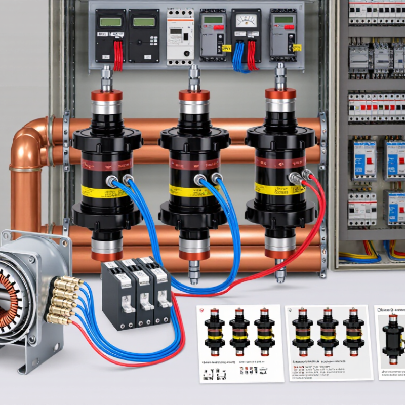
A current transformer (CT) measures alternating current without carrying the full primary current through a meter. The conductor passes through its magnetic core, creating a magnetic field that induces a smaller current in the secondary winding. A ratio such as 100:5 means 100 amperes on the primary correspond to 5 amperes on the secondary under rated conditions. That smaller signal can feed a meter or a protective relay. It also provides electrical separation between the high-current circuit and measuring equipment. A CT does not measure steady direct current in the same way, because its operation depends on changing magnetic flux. A small detail, but an important one.
Choosing a CT starts with the expected primary current and the connected equipment’s input rating. Check the burden, meaning the load from meters, relays, and wiring; long cable runs add burden too. Accuracy class matters when readings guide billing or protection. In a switchboard, for example, a CT may fit around a busbar, but its orientation and terminal markings still need careful checking. For many CT designs, an energized primary must never be left with an open secondary. Dangerous voltage can develop. Short the secondary before disconnecting its load, following the equipment’s instructions. Real installations vary, and a neat calculation can miss a crowded panel or a longer-than-expected cable run.
Start with the system’s actual operating conditions, not just the largest number on a panel. Record the AC current range, voltage, frequency, and number of phases. Note the conductor size and available space around it. A CT’s opening must fit the conductor comfortably, without forcing a tight bend. Check whether the installation is indoors or exposed to heat, dust, or moisture.
Then decide what the measurements need to do. A meter tracking everyday energy use may require different accuracy from a protective relay responding to a fault. Choose a ratio that captures normal load clearly while allowing for realistic peaks. An oversized ratio can make low loads harder to measure accurately. An undersized one may not cover expected current. Small loads matter, too. Confirm the required secondary output, such as 1 A or 5 A, and check that the connected instruments’ burden stays within the CT rating.
I have seen selections based on nominal load alone; that can miss seasonal peaks or future equipment. The details deserve a second look.
Installation and safety requirements also shape the choice. Verify the accuracy class, insulation rating, and mounting arrangement against the application. For protection, confirm the CT’s performance under anticipated fault conditions with a qualified engineer. Never leave an energized CT secondary open; use approved shorting procedures during servicing.
Measurements can be imperfect. Document the assumptions, then revisit them when the load changes.
Choosing a current transformer starts with the current ratio. Match the primary rating to the circuit’s expected operating range, not just its largest possible reading. A 400:5 CT, for example, produces 5 A at 400 A primary current. If normal load is much lower, readings may lose useful resolution. Numbers matter. Check the secondary input required by the meter or relay, and leave suitable headroom for expected load changes.
Accuracy class should fit the job. Metering needs reliable readings around normal load; protection applications need suitable performance during fault currents. Compare the class at the actual current range and rated burden, using the relevant product documentation or standard. A class number alone does not tell the whole story. I have seen tidy selection sheets overlook lead length, and that small omission can matter.
Burden includes the connected meter or relay, wiring, and other devices on the secondary circuit. Add their loads, then check that the total stays within the CT’s rated burden. Long or thin secondary wires increase resistance and can reduce accuracy. Keep the wiring practical. Also, never leave an energized CT secondary open; use an approved shorting method during service. A calculation can look precise and still miss real installation details, so verify the circuit before ordering.
Choosing a current transformer starts with the conductor and the expected current range. Match the transformer ratio to the circuit’s normal load and possible peaks; an oversized ratio can make low-load readings less useful. Check the required accuracy class, frequency, and burden, including the meter and wiring. Small details matter. The cable must fit through the opening without force, and the secondary connections must suit the measuring device. A split-core design can simplify work around an existing cable, while a solid-core unit may offer a more compact fit when the conductor can be disconnected safely. A neat fit alone does not confirm compatibility.
Plan the installation before mounting the transformer. Keep the body clear of sharp edges, heat, and moving parts, and follow the device’s marked polarity; reversed orientation can affect directional readings. Check that the secondary terminals are secure and that the leads are routed away from sources of electrical noise. Never leave a CT secondary open while its primary circuit is energized; follow the manufacturer’s instructions for shorting and connection procedures. After installation, compare the reading with a suitable reference under a known load. If results seem inconsistent, recheck the ratio, burden, polarity, and wiring. It is easy to blame the meter too soon.
Choosing a current transformer starts with the circuit and the people working near it. Confirm the primary current, system voltage, frequency, and installation location. Check that insulation ratings and clearances suit the equipment. A unit that fits the panel may still be unsuitable for the circuit.
Safety depends on correct secondary wiring. Never leave a current transformer’s secondary open while primary current is flowing; dangerous voltage can develop. Use suitable shorting terminals during testing, and make sure the secondary is grounded as required by the design. Keep the ratio, polarity, and terminal markings visible. One detail is easy to miss: a tidy enclosure does not prove the wiring is correct.
Compatibility also includes burden and accuracy class. Add the connected meter, relay, and lead burden, then compare the total with the transformer’s rated burden. Check the required protection or measurement performance, not just the nominal ratio. Review the applicable standard and its current edition for the project and region, such as IEC 61869-2 or IEEE C57.13 where relevant. Confirm documentation and test records match the exact unit. I would still verify the labels after installation; drawings can be right while field markings are not.
Example calculation: 100 m one-way of 2.5 mm² copper cable gives a 200 m circuit-loop resistance of approximately 1.4 Ω at 20 °C. Lead burden is approximately I²R: 1.4 VA at 1 A and 35 VA at 5 A. Check that the CT’s rated output burden covers the leads and connected instruments, and match its ratio, secondary current, and accuracy class to the application. Never leave an energized CT secondary open; short it before disconnecting instruments. For applicable instrument-transformer requirements, consult IEC 61869-2 and local regulations.
It measures alternating current by producing a smaller secondary current. The primary conductor passes through its magnetic core.
At rated conditions, 100 amperes on the primary produce 5 amperes on the secondary. Check the meter’s required input.
Not in the same way. Its operation depends on changing magnetic flux.
Match it to the circuit’s usual operating range, not only its maximum current. A 400:5 unit produces 5 amperes at 400 amperes.
Burden includes meters, relays, and secondary wiring. Long or thin cables add resistance and can affect accuracy.
Match it to the task and expected current range. Metering and protection may need different performance. A class number alone is not enough.
Dangerous voltage can develop. Use an approved shorting method before disconnecting the load.
Check orientation, terminal markings, and wiring length. A crowded panel can complicate a tidy calculation. I would verify the circuit again.
Choosing a Current Transformer begins with understanding how it converts high current in a conductor into a smaller, measurable signal for monitoring or protection. First identify the electrical system, including its operating current, voltage, frequency, and intended use. These details help determine the appropriate transformer type and ensure it can perform reliably under normal operating conditions.
Next, select a current ratio that suits the expected load, along with an accuracy class and burden that meet the measurement requirements. Consider the design and installation method, available space, conductor arrangement, and ease of maintenance. Before finalizing the selection, check that the transformer is compatible with connected instruments and protection devices, and that its insulation, ratings, and installation arrangements meet applicable technical standards and safety requirements. A careful selection process supports dependable measurements and safe, effective operation.