 CEMarked CEMarked
Choosing the right Auto Transformer starts with the job it must do, not its catalog price. Will it boost or reduce voltage for a motor, a test bench, or a production line? Record the supply voltage, required output, load current, starting demand, and operating hours. A motor that draws a heavy inrush current can challenge a unit sized only for its running load. Small details matter.
The wider power context makes careful selection more important. The International Energy Agency’s Electricity 2024 report projected average global electricity-demand growth of about 3.4% annually from 2024 through 2026. That figure does not determine which transformer a facility needs, but it highlights the value of planning for changing loads and dependable operation. Compare continuous and short-term ratings, efficiency, temperature rise, cooling, enclosure, and installation conditions. Check the manufacturer’s documentation and have a qualified electrical professional verify the design.
An autotransformer uses a shared winding, so it does not provide galvanic isolation between input and output. That distinction can matter as much as voltage and kVA. Confirm the required protection, grounding arrangement, and applicable equipment standards for the installation. A compact unit may fit neatly beside a machine. Yet space savings alone are not a specification. That assumption deserves a second look. The right choice balances electrical performance, safety needs, operating conditions, and future capacity—based on measured requirements, not guesswork.
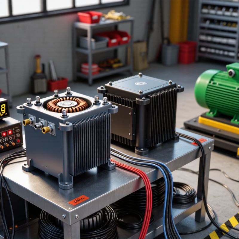
An autotransformer uses one continuous winding with electrical taps, rather than separate primary and secondary windings. The supply connects across part or all of the winding, while the output uses a selected section. This arrangement lets the transformer raise or lower AC voltage according to the turns ratio. One winding. Shared copper.
Because input and output share a winding, an autotransformer does not provide electrical isolation. That distinction is easy to miss when comparing voltage ratings alone. For example, a unit can convert a 120-volt supply to 100 volts, but the output remains electrically connected to the input circuit. Check whether your equipment requires isolation, and consult a qualified electrical professional when the installation is unclear.
A practical choice starts with the source voltage, required output voltage, and the load’s power demand. A small voltage mismatch may suit a compact unit; a motor or other load with a high starting current may need additional capacity. Also check frequency, duty cycle, enclosure, cooling, and protective devices. Read the rating plate carefully. I’d avoid choosing by wattage alone: actual load behavior, especially at startup, can change the required rating.
| Selection Factor | What to Check | Realistic Example | Practical Guidance |
|---|---|---|---|
| How an autotransformer works | An autotransformer uses one continuous winding with electrical connections, or taps, at different points. Part of the winding is shared by the input and output circuits. | A fixed-ratio unit can convert a 480 V supply to a 400 V output using a suitable winding tap. | The shared winding makes the design compact and material-efficient, but the input and output are electrically connected rather than galvanically isolated. |
| Input and output voltage | Confirm the nominal supply voltage, required load voltage, permitted voltage variation, and whether the system is single-phase or three-phase. | A three-phase 480 V supply serving equipment rated for 400 V requires a 480-to-400 V conversion. | Check the equipment nameplate and local supply conditions. Do not choose a unit based only on its nominal voltage ratio. |
| Frequency | Match the transformer’s rated frequency to the supply frequency and the equipment requirements. | A unit rated for 50 Hz should not automatically be assumed suitable for 60 Hz, or vice versa; suitability depends on its design and ratings. | Verify the frequency rating on the transformer documentation. Frequency affects core flux and operating conditions. |
| Load capacity | Determine the load’s apparent power in kVA, including continuous demand and relevant starting or short-duration loads. | A three-phase, 30 kVA load at 400 V draws about 43.3 A: 30,000 ÷ (√3 × 400). | Select a unit rated for the actual load and operating duty. Consider motor starting current and other transient demands where applicable. |
| Input and output current | Check the current on both sides of the transformer, as the voltage change means the currents will differ. | For an ideal three-phase 30 kVA load, current is about 36.1 A at 480 V and 43.3 A at 400 V. | Use the manufacturer’s ratings and applicable electrical codes when selecting conductors, protective devices, and disconnects. |
| Winding capacity and voltage difference | For an autotransformer, only the portion of power associated with the voltage difference is transferred magnetically; the rest is transferred conductively through the shared winding. | For 480 V to 400 V at 30 kVA, the voltage difference is 80 V. The approximate transformed portion is 30 × (80 ÷ 480) = 5 kVA. | Do not mistake the transformed portion for the required load rating. Confirm both the unit’s output kVA rating and its winding ratings. |
| Fixed-ratio or variable output | Decide whether the application needs one fixed conversion ratio or an adjustable output voltage. | A fixed-ratio model suits a permanent 480-to-400 V conversion; a variable autotransformer suits controlled voltage adjustment within its specified range. | Check the adjustment range and current rating across that range. A variable autotransformer generally does not provide electrical isolation. |
| Isolation and earthing | Assess whether the application requires galvanic isolation between the supply and the load. | An autotransformer’s input and output share a winding and electrical connection. | If isolation is required for safety, system design, or equipment requirements, specify an isolation transformer instead and review the earthing arrangement with a qualified electrician. |
| Voltage regulation and load behavior | Consider expected supply variation, load variation, and the voltage tolerance of connected equipment. | A fixed tap provides a fixed nominal ratio; it does not actively regulate the output as the supply or load changes. | Where tighter voltage control is needed, assess a suitable regulator or adjustable solution rather than assuming a fixed-ratio autotransformer will stabilize voltage. |
| Duty, cooling, and environment | Check continuous or intermittent duty, cooling method, ambient temperature, enclosure, and installation location. | An indoor, continuously loaded installation may need a different enclosure and thermal rating from a short-duration test-bench application. | Follow the unit’s temperature, ventilation, mounting, and environmental limits. Allow required clearance for cooling. |
| Protection and installation | Review overcurrent protection, short-circuit withstand, switching, conductor sizing, and applicable electrical standards. | Protection requirements depend on the installation, supply fault level, transformer design, and local regulations. | Have a qualified electrical professional coordinate protection and installation. Use the manufacturer’s instructions and applicable codes. |
It uses one continuous winding with electrical taps. The selected winding section raises or lowers AC voltage.
No. Both circuits share a winding and remain electrically connected. That detail matters.
Compare source voltage, required output, and load demand. Check frequency, duty cycle, cooling, enclosure, and protection devices too.
Motors may draw extra current when starting. A rating based only on running wattage can be misleading.
It can suit applications with a voltage ratio close to 1:1. Its shared winding may reduce copper use and size.
Trace each terminal on the supplied diagram. Check neutral arrangements, grounding, fault protection, and the site wiring plan. Easy to miss.
Inspect terminal tightness, airflow openings, unusual hum, discoloration, and operating temperature. Keep dust away from cooling surfaces.
Not by themselves. Load behavior, voltage ratio, and installation conditions affect results. I’d treat a neat catalog figure cautiously.
Choosing the right Auto Transformer begins with understanding how it transfers power through a shared winding to adjust voltage. This design can be compact and efficient, but the best option depends on the equipment it will serve. First, identify the required input and output voltages, expected load, and any starting or peak demand. Then select a winding configuration that matches the application, including whether voltage needs to be stepped up or down and how the unit will connect to the electrical system.
Before making a selection, compare the transformer’s capacity and ratings with the anticipated load, and review its protection features and installation conditions, such as available space, ventilation, and operating environment. Consider efficiency alongside safety and maintenance needs: a suitable unit should operate reliably without being routinely overloaded and should allow practical inspection and upkeep. Matching these factors helps ensure the transformer fits both the electrical requirements and the conditions in which it will be used.
